4 x Set-up and installation
FA ROTEX HPSU compact (V5) •
35
4.5.16 Connection optional ROTEX
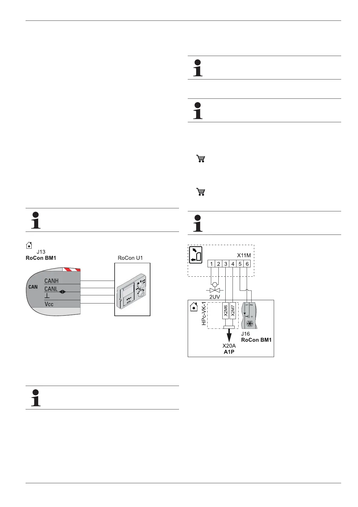
RoCon system components
The optional RoCon devices must be connected to the ROTEX
HPSU compact using a 4-core CAN bus cable (connection J13).
ROTEX recommends screened cables with the following charac-
teristics for this purpose:
– Standard to ISO 11898, UL/CSA type CMX (UL 444)
– PVC outer sheath with flame re
tardant to IEC 60332-1-2
– Up to 40 m, minimum cross-section area 0.75 mm
2
.
For greater lengths, use larger cross-section areas.
Commercially available junction boxes can be used for con-
nection of Can bus lines of several RoCon devices.
Ensure power cables, sensor cables and data bus cables are laid
se
parately from each other. Use only cable trunking with sep-
arate trays or cable trunking with sep
arators that ensure at least
2 cm spacing. Cable crossings are permissible.
The entire RoCon system can have a maximum of 16 devices
connected with a total cable length up to 800 m.
ROTEX Room station RoCon U1
For the remote setting of operating modes and room target tem-
peratures from a different room, a separate room station RoCon
U1 can be connected for each heating circuit.
ROTEX Mixer module RoCon M1
The ROTEX HPSU compact can be connected to the RoCon M1
mixer module, which is controlled via the RoCon HP electronic
controller.
The connection of the CAN data bus
lines is identical to the
fig. 4-40 to connection J13 of the ROTEX HPSU compact.
Internet gateway ROTEX RoCon G1
The controller can be connected to the internet via the optional
RoCon G1 gateway. This means that the ROTEX HPSU compact
can be controlled remotely via mobile phone (using an App).
4.5.17 Connection of the ROTEX HP convector
– Electrical connection of the ROTEX HP convector with the fol-
lowing accessories in accordance with fig. 4-41 as a change-
over contact (heating/cooling) on the basic module.
– Connect genuine ROTEX connection cable (HP
c-VK-1
14 20 15) on ROTEX HPSU compact …(H/C)… (with
cooling function), so that the ROTEX HP convector switches
the operating mode (heating/cooling) together with the
ROTEX HPSU compact.
– Install and connect 2-way valve (2UV) (HPC-RP
14 20 13) in
ROTEX HP convector if necessary. Adjust
its regulation so that the 2-way valve (2UV) provides isolation
if there is no demand for this unit.
This component has a separate manu
al attached,
including among other things instructions for installation
and operation.
Fig. 4-40 Connection room station RoCon U1
This component has a separate manual attached,
including among other things instructions for installation
and operation.
This component has a separate manual attached,
including among other things instructions for installation
and operation.
This component has a separate manual attached,
including among other things instructions for installation
and operation.
Mode (heating/cooling) can only be switched on the
ROTEX
HPSU compact.
Fig. 4-41 Connecting the ROTEX HP convector to the ROTEX HPSU
compact
 Loading...