4 x Set-up and installation
FA ROTEX HPSU compact (V5) •
37
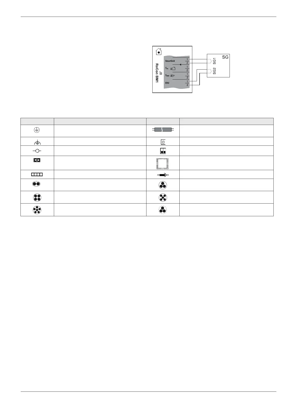
4.5.20 Connection intelligent controller
(Smart Grid - SG)
Once the function is activated by parameter [SMART GRID] = 1
(see operating manual for the control unit), depending on the sig-
nal from the energy supply company, the heat pump is switched
to Stand-b
y, Normal or an operating mode with higher tempera-
tures.
To do so, the potential-free contacts SG1/SG2 of the intelligent
controller must be connected to the J8 plug, connections Smart
Grid and EVU, on the RoCon BM1 circuit board (see fig. 4-44).
As soon as the Smart Grid function is active, the HT/NT function
is deactivated automatically. Depending on the value of the pa-
rameter [Mode SG] the heat pump op
erated in a different manner
(see operating manual for the control unit).
4.5.21 Symbols and legend keys on connection and circuit diagrams
Fig. 4-44 Connection Smart Grid
Symbols Explanation Symbols Explanation
Safety earthing
External cabling (number of individual cores and
the mains voltage are partially quoted.)
Low external voltage earthing Pushbutton
Connection terminal DIP switch
Plug connection Optional component
Terminal rail Plug and socket connection
2-core cabling (non-screened) 3-core cabling (non-screened)
4-core cabling (non-screened) 5-core cabling (non-screened)
6-core cabling (non-screened) Shielded cabling (for example 3-strand)
Tab. 4-2 Symbol explanations for connection and circuit diagrams
 Loading...