30
FA ROTEX HPSU compact (V5) •
4 x Set-up and installation
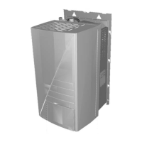
4.5.8 Open controller housing and making the
electrical connections
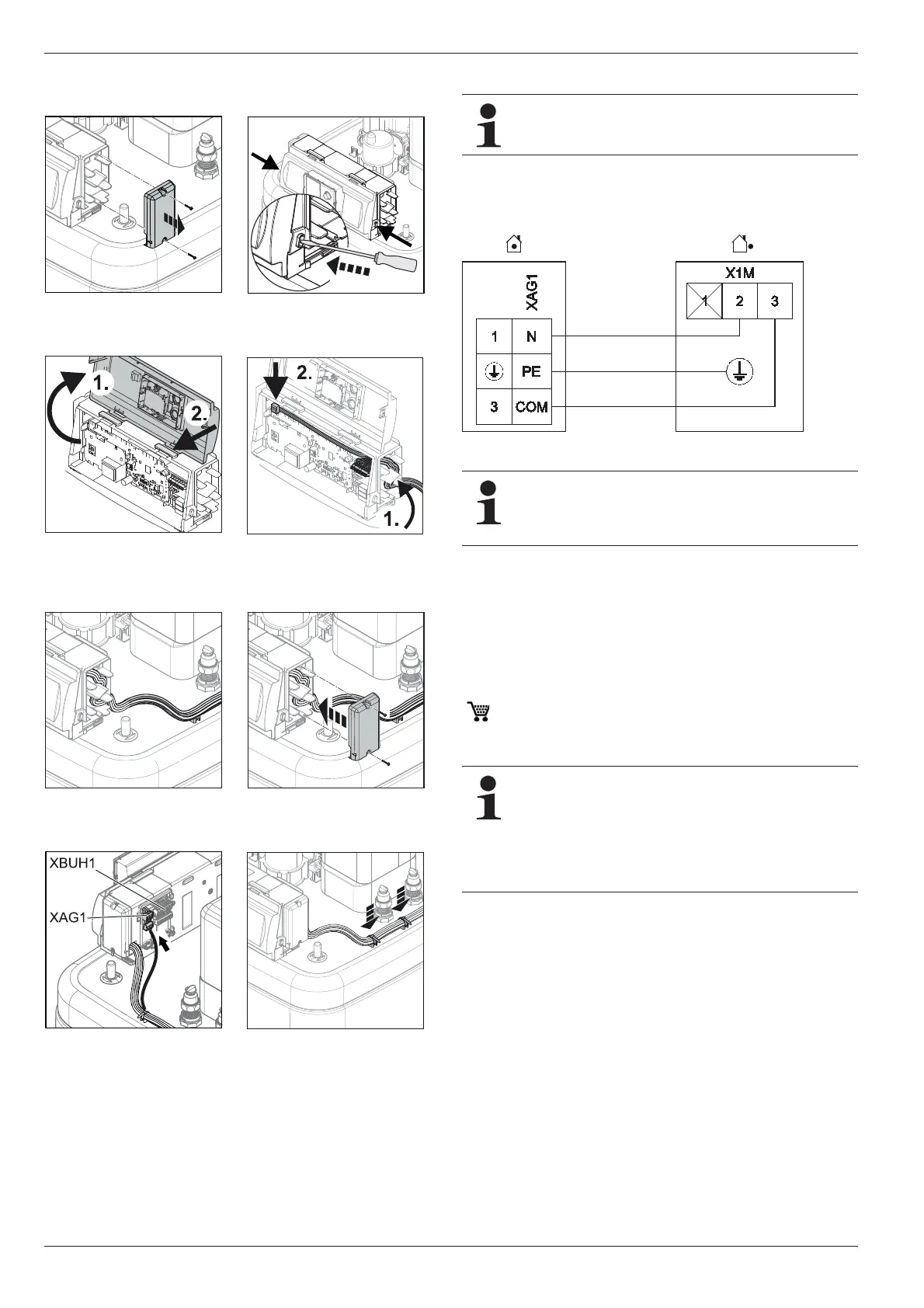
4.5.9 Connection of exterior heat pump unit RRLQ
Ɣ Dismount the protective cover (see section).
Ɣ Connect the exterior heat pump unit to the terminal strip
XAG1 (see fig. 4-28, fig. 4-30).
4.5.10 Connection of external temperature sensor
RoCon OT1
The exterior heat pump unit of the ROTEX HPSU compact has a
built-in exterior temperature sensor which is used to regulate the
inflow temperature depending on the weather, with frost pro-
tection function.
With the optional outside temperature sensor RoCon OT1
( 15 60 70), wh
ich is installed on the north side of the building,
you can optimise the weather-dependent flow temperature
control.
Choose a location at about one third of the building height
(minimum distance from floor: 2 m) at the coldest side of the
building (North or North-East). Thereby, exclude the proximity of
external heat sources (chimney, air shafts) and direct sunshine.
Ɣ Place external temperature sensors in such a way that the
cable exit points face downwards (prevents humidity ingress).
Fig. 4-22 Dismount right housing
cover.
Fig. 4-23 Unlock front panel.
Fig. 4-24 Open front panel and
place in assembly posi-
tion.
Fig. 4-25 Route cabling into the
regulator and make the
electrical connections.
Fig. 4-26 Lay cables in the right
housing cover.
Fig. 4-27 Install the right housing
cover.
Fig. 4-28 Make the electrical con-
nections to the rear of
the ho
using
(see section 4.5.1).
Fig. 4-29 Fasten cabling on the
stor
age container.
This component has a separate manual attached,
including among other things instructions for installation
and operation.
Fig. 4-30 Connection of exterior heat pump unit
When switching off the heat pump exterior unit using a
switching system prescribed by the energy supply com-
pany (EVU), the internal ROTEX HPSU compact
de
vice is not disconnected (see section 4.5.19).
If the ROTEX HPSU
compact is used in a CAN bus
system as a master ("Terminal function" for the remote
control of other data bus devices), the exterior temper-
ature sensor RoC
on OT1 must be connected directly
to the regulator RoCon HP on the master and not to
the remote controlled device (mixer circuit module
RoCon M1 or a different heat generator).
 Loading...