46
FA ROTEX HPSU compact (V5) •
6 x Decommissioning
6 Decommissioning
6.1 Temporary shutdown
If the ROTEX HPSU compact is not needed for a long time, it can
be temporarily decommissioned.
ROTEX therefore recommends that you do not disconnect the
system from power supply, but rather only place it in "Stand-By
Mode" (consult the operating manual for the control system).
The system is then protected from frost. The pumps and valve
protection functions are active.
If it is not possible to guarantee the power supply when there is
danger of frost,
– completely discharge the ROTEX HPSU compact on the
water side, or
– suitable antifreeze measures must be take
n for the connected
heating system and hot water storage tank (e.g. draining).
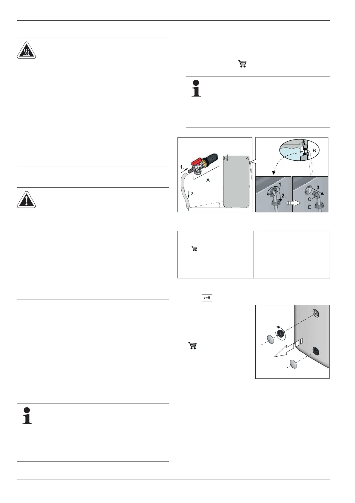
6.1.1 Draining the storage tank
Ɣ Disconnect ROTEX HPSU compact from the power supply.
Ɣ Con
nect the drain hose to the KFE filling connection
(accessory KFE BA, 16 52 15) (fig. 6-1, item A) and run
to drainage point that is at least soil deep.
Tab. 6-1 Legend from fig. 6-1 to fig. 6-6
Without solar installation
WARNING!
Danger of scalding and flooding when
opening the solar return flow coupling or
heating and hot water pipes due to es-
caping hot water.
Ɣ Only drain the storage tank container
or heating system
– when they have been left to cool
sufficiently,
– with a suitable device for the safe
draining or catching of escaping
water,
– wearing appropriate protective
clothing.
CAUTION!
A heating system that is shut down can
freeze in the event of frost and may
suffer damage.
Ɣ If there is any risk of frost, drain any
water from the decommissioned
heating system.
Ɣ If the heating system is not drained
and there is a risk of frost, the power
supplies must be secured and the
external main switch must remain
switched on.
If there is a danger of frost and the power supply cannot
be guaranteed for just a few days, the unit's excellent
heat insulation means that the ROTEX HPSU compact
does not have to be drained, provided that the storage
tank temperature is monitored regularly and does not
fall below +3 °C.
However, there is no frost p
rotection for the connected
heat distribution system through this.
If no KFE filling connection is available, the con-
nection piece (fig. 6-1, item C) can alternatively be
removed from the safety overflow (fig. 6-1, item B)
and used.
Once the draining process is complete, this must be
replaced before the heating system can be started
again.
Fig. 6-1 Connecting the drain-
age hose
Optional: Removing the connec-
tion piece from the safety overflow
A KFE filling connection
(accessory KFE BA,
16 52 15)
B Safety overflow
C Hose connection piece for
safety overflow
D Clamping piece
E Threaded piece
F Sealing plug
G Connecting angle
X Valve insert
Ɣ Remove the cover plate
from the filling and
emptying fitting.
Ɣ W
hen using the KFE
filling connection
(accessory KFE BA,
16 52 15):
Remove the cover plate
fro
m the handle and
unscrew the threaded
piece (fig. 6-2, item E)
from the storage tank con-
tainer.
Fig. 6-2 Unscrew threaded piece
E
 Loading...