8 x Errors, malfunctions and messages
FA ROTEX HPSU compact (V5) •
67
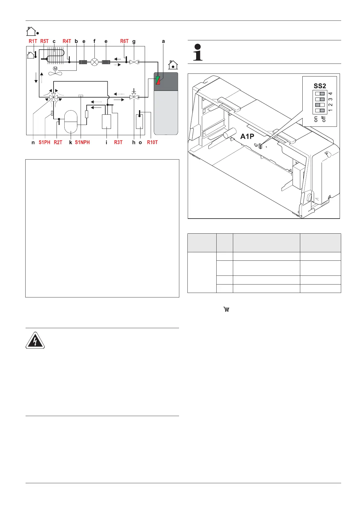
8.4 Monitoring and configuration DIP Switch
Ɣ Disconnect the system from the power supply.
Ɣ Ope
n the control housing and remove the RoCon BM1 board
(see chapter 4.5.8).
Ɣ Check th
e DIP switch setting on the A1P circuit board of the
ROTEX HPSU compact, adjust where necessary
(see tab. 8-4).
The factory preset may only be changed if e.g. an
op
tional accessory was connected.
Ɣ Rep
lace the RoCon BM1 switch board, close the control
housing and reconnect the power supply.
* If you intend to run the internal heating circulation pump continuously, it will
need to be connected to the circuit board A1P, plug X17A, via a separate con-
nection cable ( E1400132).
Tab. 8-4 DIP switch settings
8.5 Emergency operation
In the case of incorrect setting in the electronic control system,
emergency heating operation can be maintained by activating the
special "Manual Operation" function on the control unit (see op-
erating manual for the control unit).
If the 3-way valves are intact, the ROTEX HPSU compact
switches to Heating mode. The necessary flow temperature can
be adjusted with the rotary switch.
Fig. 8-4 Components in the heat pump circuit (simplified diagram)
a Plate heat exchanger (condensator)
b Ventilator motor
c Lamella heat exchanger (evaporator)
eFilter
f Electronic expansion valve
g Service valve (liquid line)
h Service valve with mainte
nance connection (gas line)
i Accumulator
k Coolant compressor
n 4-way diverter valve (—> Heat, ·
···> Cool)
o Inverter board
R1T External temperature sensor
R2T Discharge temperature sensor (coolant compressor)
R3T* Suction temperature sensor (coolant compressor)
R4T* Temperature sensor lamella heat exchanger-input
R5T Temperature sensor lamella heat exchanger-middle
R6T* Temperature sensor liquid line (t
L2
)
R10T* Temperature sensor on inverter board
S1PH High pressure switch
S1NPH Pressure sensor
* Only with 11-16 kW heat pump external devices.
Tab. 8-3 Legend for fig. 8-4
WARNING!
Touching live parts can result in an
electric shock and lead to potentially
fatal injuries and burns.
Ɣ Before beginning work on live parts,
disconnect all of the systems circuits
from the power supply (switch off
main switch, disconnect fuse) and
secure against unintentional restart.
DIP switch settings are not recognised until a brief inter-
ruption to the power supply.
Fig. 8-5 Setting of DIP switch SS2
DIP
switch
No. Designation Factory setting
SS2
1 Do not change. OFF
2
Domestic hot water
generation
ON
3 Pump continuous running* OFF
4 Do not change. OFF
 Loading...