78
FA ROTEX HPSU compact (V5) •
10 x Technical data
10.2 Characteristic lines
10.2.1 Sensor characteristic lines
Nominal EER A35/W18 3.65 / 3.65
3.32 / 2.96 /
2.72
3.65 / 3.65
3.32 / 2.96 /
2.
72
Nominal EER A35/W7 2.51 / 2.51
2.72 / 2.47 /
2.29
2.51 / 2.51
2.72 / 2.47 /
2.
29
Max. heating output A-7/W35
kW 5.3 / 6.4 8.8 / 11.7 /
12.3
5.3 / 6.4 8.8 / 11.7 /
12
.3
Max. heat output A2/W35
kW 6.4 / 7.7 9.1 / 10.9 /
11.4
6.4 / 7.7 9.1 / 10.9 /
11.4
Max. heat output A7/W35
kW 8.4 / 10.2 11.4 / 14.6 /
16.1
8.4 / 10.2 11.4 / 14.6 /
16
.1
Max. heat output A10/W35
kW 8.8 / 10.5 11.9 / 15 /
16.5
8.8 / 10.5 11.9 / 15 /
16
.5
Max. cooling output A35/W18
kW 7.3 / 8.4 15.1 / 16.1 /
16.8
7.3 / 8.4 15.1 / 16.1 /
16.8
Max. cooling output A35/W7
kW 5.5 / 6.4 11.7 / 12.6 /
13.1
5.5 / 6.4 11.7 / 12.6 /
13
.1
* Not all the equipment mentioned here is offered in some
countries because of the various different country-specific
connection conditions.
1) T
CW
Cold water input temperature = 10 °C
T
DHW
Hot water draw-off temperature = 40 °C
T
S
Storage target temperature (charge state before draw-
ing off)
2) With a reference spacing of 1 m.
3) Number of individual wires in the connection cable,
including protective
earth. The cross-section of the individual lines is dependent on the current
load, the length of the connection cable and the respective legal provi-
sions.
4) Hot water storage tank only to be charged using a heat pump, withou
t a
backup heater.
Tab.
10-2 Basic data ROTEX HPSU compact 508/516
Type ROTEX HPSU compact
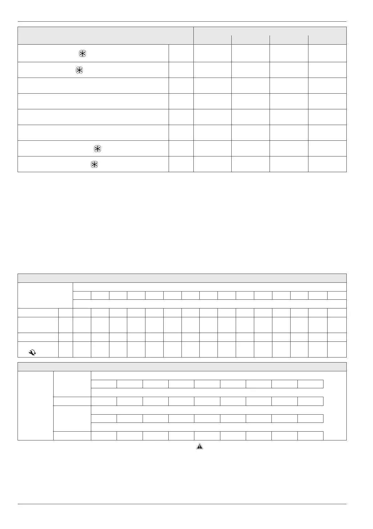
508 DB 516 DB 508 BIV 516 BIV
Temperature sensor
Measured temperature in °C
-20-100 102030405060708090100110120
Sensor resistance in kOhm according to standard or manufacturer's indications
t
DHW2
NTC
— — 811.5 480.6 293.2 183.8 118.2 77.7 52.3 35.8 25.1 17.8 12.9 9.5 7.1
t
Au
(RoCon OT1),
t
DHW1
NTC
98.66 56.25 33.21 20.24 12.71 8.20 5.42 3.66 2.53 1.78 1.28 0.93 0.69 0.52 0,36
t
Au
(R1T) NTC
197,8 112,0 65,8 40.0 25.0 16.1 10.6 7.2 5.0 3.5 2.5
——— —
t
V1
, t
V2
, t
V, BH
,
t
R2
NTC
197.80 120.00 65.84 39.91 24.95 16.04 10.58 7.14 4.77 3.19 2.36 1.74 1.33 1.07 0.84
FLS Sensor (Flow/Temperature)
FLS
(t
R1
/ V1)
V1
Measured flow in l/min
10.0 20.0 30.0 40.0 50.0 60.0 70,0 80.0 —
Sensor output frequency in Hz
(14 - 229 Hz)
28 54 81 108 135 162 188 215 —
t
R1
Measured temperature in °C
10.0 20.0 30.0 40.0 50.0 60.0 70,0 80.0 90.0
Sensor resistance in Ohm
(Pt 1000)
1039 1077 1116 1155 1194 1232 1270 1308 1347
Tab. 10-3 Sensor Table ROTEX HPSU compact
Maximum tightening torque of sensor =10 Nm.
 Loading...