Insert the cable into the terminal box
1. Unscrew the cable entry plate.
2. Drill the required number of holes or threads in the required size in the cable entry plate.
Ensure that the cable entry plate can be assembled after drilling and that it features
sufficient stiffness.
3. Fit the required cable glands.
4. Route the cables through the cable glands.
5. Fit the cable entry plate to the terminal box with the assembled cables.
6. Connect the ends of the cables to the terminals in accordance with the circuit diagram. The
circuit diagram is located in the cover of the terminal box.
Refer to Chapter "Connecting cables ..." for more information.
6.4.3 Inserting the cable into the 1XB.. terminal box with ring seal
The following terminal boxes may be equipped with an onion sealing ring.
Table 6-5 Terminal boxes with onion sealing ring
Terminal box Onion sealing ring
1XB9600 Standard design
1XB1621, 1XB1631, 1XB1634 Optional
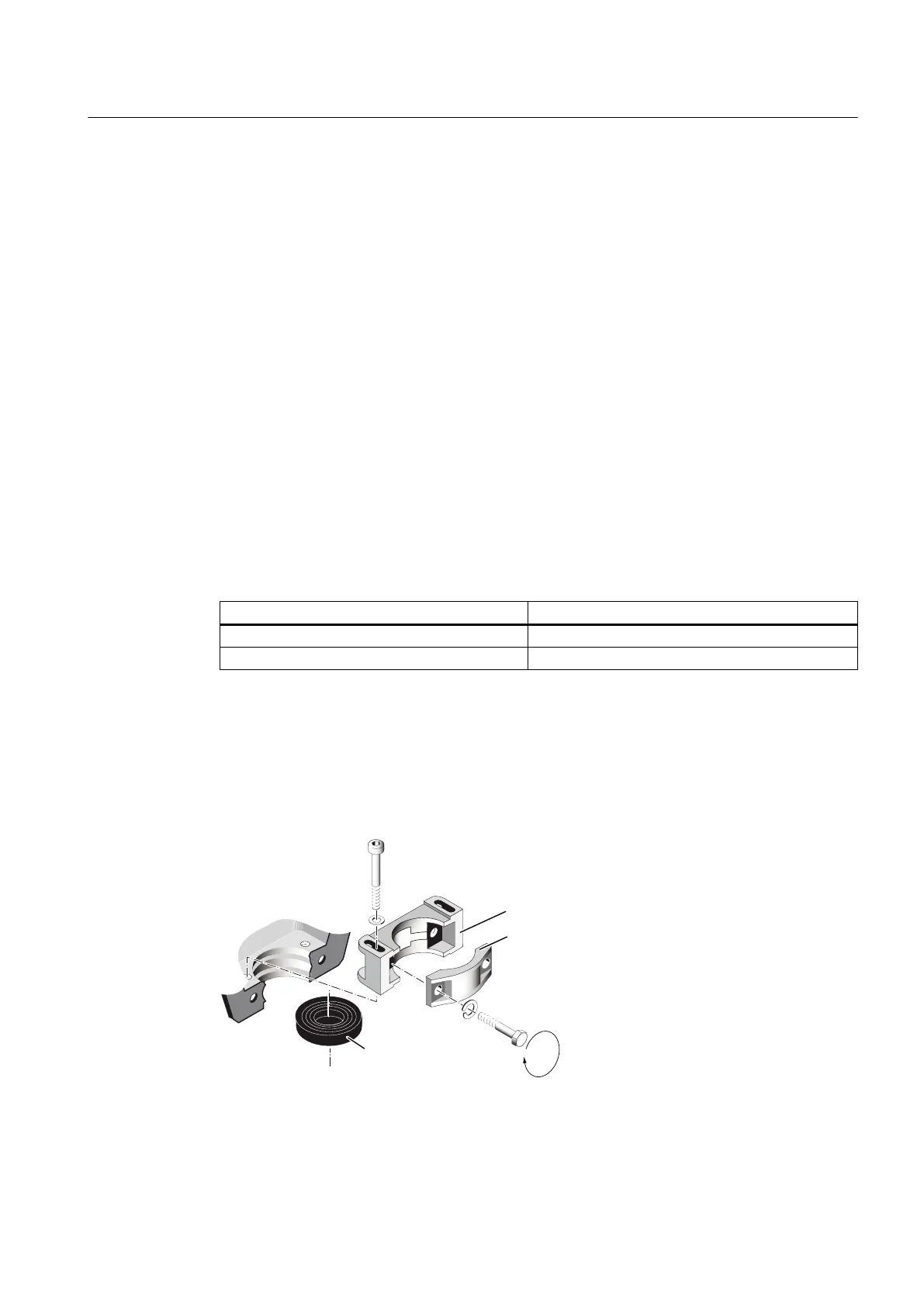
The connecting cable is sealed at the cable entry location using a cut-out sealing insert and
is fastened using a strain relief device.
Bringing cables into the terminal box and connecting them
The terminal box is opened, the cable cut to the correct length and stripped back. Make sure
that no external forces are acting on the cable connection.
Image 6-7 Strain relief device and sealing insert
Electrical connection
6.4 Connection
SIMOTICS TN Series N-compact 1LA8
Operating Instructions 05/2016 69

 Loading...


