When performing any installation work, you must always take care to ensure that all
equipotential bonding measures remain effective.
6.4.10 Stepless mating face for sealing in the terminal box cover (not for GT640)
The sealing face of the terminal box cover is formed by the terminal box enclosure and the
cable entry element. Therefore make sure these parts are correctly aligned, so as to ensure
the seal and hence the degree of protection.
Align the cable entry support and the cable entry plate to the terminal box enclosure so that
the sealing surface between the terminal box and the terminal box cover form a flat face. There
must be no steps in the sealing area.
6.4.11 Minimum air clearances
After proper installation, verify that the minimum air clearances between non-insulated parts
are maintained. Be aware of any protruding wire ends.
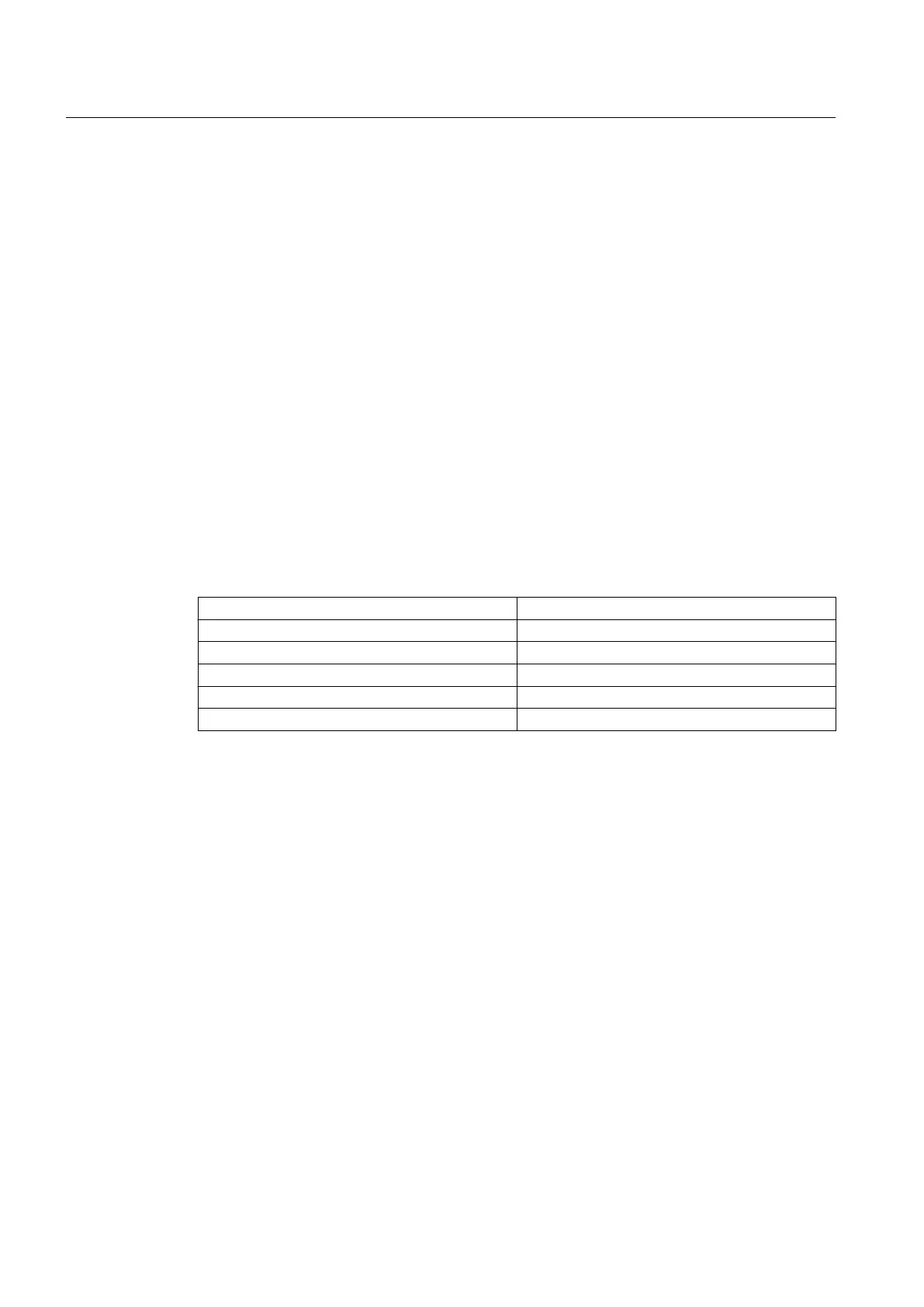
Table 6-6 Minimum air clearance dependent on rms value of the alternating voltage U
rms
Rms value of the alternating voltage V
rms
Minimum air clearance
≤ 500 V 8 mm
≤ 630 V 10 mm
≤ 800 V 12 mm
≤ 1000 V 14 mm
≤ 1250 V 18 mm
Values apply at an installation altitude of up to 2000 m.
When determining the required minimum air clearance, the voltage value in the table may be increased
by a factor of 1.1, so that the rated input voltage range is taken into account during general use.
Electrical connection
6.4 Connection
SIMOTICS TN Series N-compact 1LA8
74 Operating Instructions 05/2016

 Loading...


