B-2
TP27, TP37 Equipment Manual
Release 01/00
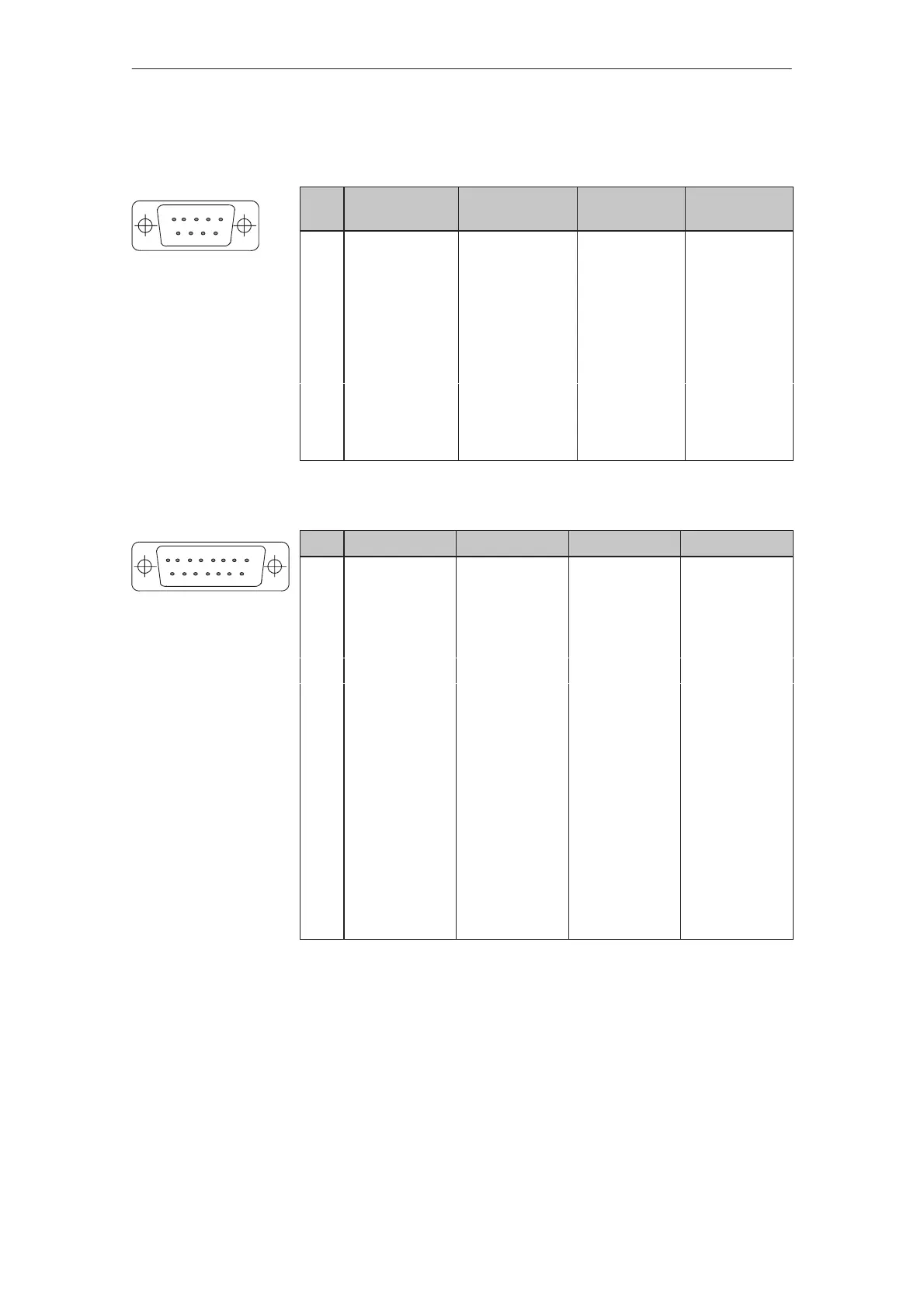
Pin assignment of the 9–pin Sub-D socket
(Configuration via DIL switch, see Chapter 12.2.3):
Pin General PROFIBUS-DP
MPI
RS422 RS485
1
2
3 Data B TxD (B) Data B
4 RxD (B)
5 GND (floating )
6 +5 V (floating )
7
8 Housing Data A TxD (A) Data A
9 RxD (A)
Pin assignment of the 15–pin Sub–D socket:
Pin General TTY RS42 RS485
1 Housing
2 RxD–
3 RxD (B)
4 TxD (B) Data B
5 RxD (A)
6 TxD+
7 TxD–
8 Housing
9 RxD+
10 TxD (A) Data A
11 +24 V
12 GND (5 V)
13
14 +5 V
15 GND (24 V)
IF1B
IF3 (TP37 only)
Interface Assi
nments
51
96
81
15 9
 Loading...