Operation
104 Revision 03 * INSTALLATION AND OPERATING INSTRUCTIONS 8DJH * 500-8067.9
16.1 Operations
Ö Check ready-for-service indicator a.
Ö Remove padlock f (optional).
Ö Operate control gate d (optional depending on situation) to release the switching
gate and hold it tight.
Ö Insert operating lever s and move straight to the desired switch position.
Ö Remove operating lever. The control gate moves to the center position automatically.
Ö Refit padlock at desired position.
r The locking device (optional depending on situation) of the switching gate can be
padlocked in all three switch positions.
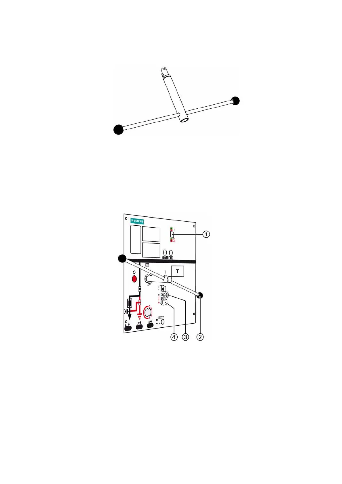
Fig. 72: Standard: Single-lever operation wth black handle and
coding as universal lever. Alternative 1: One operating
lever with red handle for earthing and de-earthing, and
one operating lever with black handle for load breaking.
Alternative 2: Single-lever operation with anti-reflex
lever, with and without coding.
Fig. 73: Control board of three-position switch
a
Ready-for-service indicator
s
Operating lever
d
Control gate/locking device
(option for spring-operated mechanism)
f
Padlock (option)

 Loading...