500-8067.9 * INSTALLATION AND OPERATING INSTRUCTIONS 8DJH * Revision 03 31
Description
7.7 Current and voltage transformers
Current and voltage transformers
Current transformers
• According to IEC 60 044-1/ VDE 0414-44-1
Voltage transformers
• According to IEC 60 044-2 / VDE 0414-44-2
Technical data The technical data of the current and voltage transformers are given in the associated
order documents.
7.8 Protection and control equipment
Protection and control equipment is equipped according to the customer’s
specifications. The devices are normally installed in the low-voltage compartment and/or
in the low-voltage niche. For details please refer to the relevant circuit documentation.
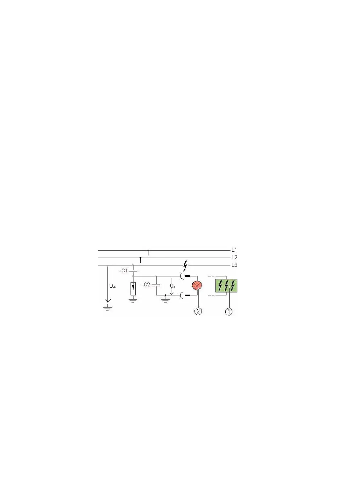
7.9 Voltage detecting systems
For voltage detection according to IEC 61243-5/VDE 0682-415 with:
• HR system (standard)
• LRM system (option)
• VOIS+, VOIS R+ (option)
• Integrated voltage detecting system CAPDIS-S1+/-S2+(option)
• -C1: Capacity integrated into bushing
• -C2: Capacity of the connection leads and the voltage indicator to earth
•U
LE
=U
N
/√3 during rated operation in the three-phase system
•U
2
=U
A
=Voltage at the capacitive interface of the switchgear or at the voltage indicator
Fig. 23: Voltage detecting system via capacitive voltage divider
(principle)
a
CAPDIS-Sx+ fixed-mounted
s
HR/LRM indicator plugged in
 Loading...