Installation
68 Revision 03 * INSTALLATION AND OPERATING INSTRUCTIONS 8DJH * 500-8067.9
11.6 Preparing the foundation
Please observe the following items when preparing the foundation:
• A suitable foundation can be a false floor, a double floor or a reinforced-concrete
foundation. The reinforced-concrete floor must be equipped with foundation rails for
supporting the panels.
• As for design and construction of the foundation, the relevant standards DIN 43 661
“Fundamentschienen in Innenanlagen der Elektrotechnik” (Foundation rails in
electrical indoor installations) and DIN 18 202 “Maßtoleranzen im Hochbau” (Blatt 3)
(Measuring tolerances in structural engineering (Sheet 3)) apply.
• The dimensions of the floor opening and the fixing points of the switchgear frame are
given in the switchgear documentation.
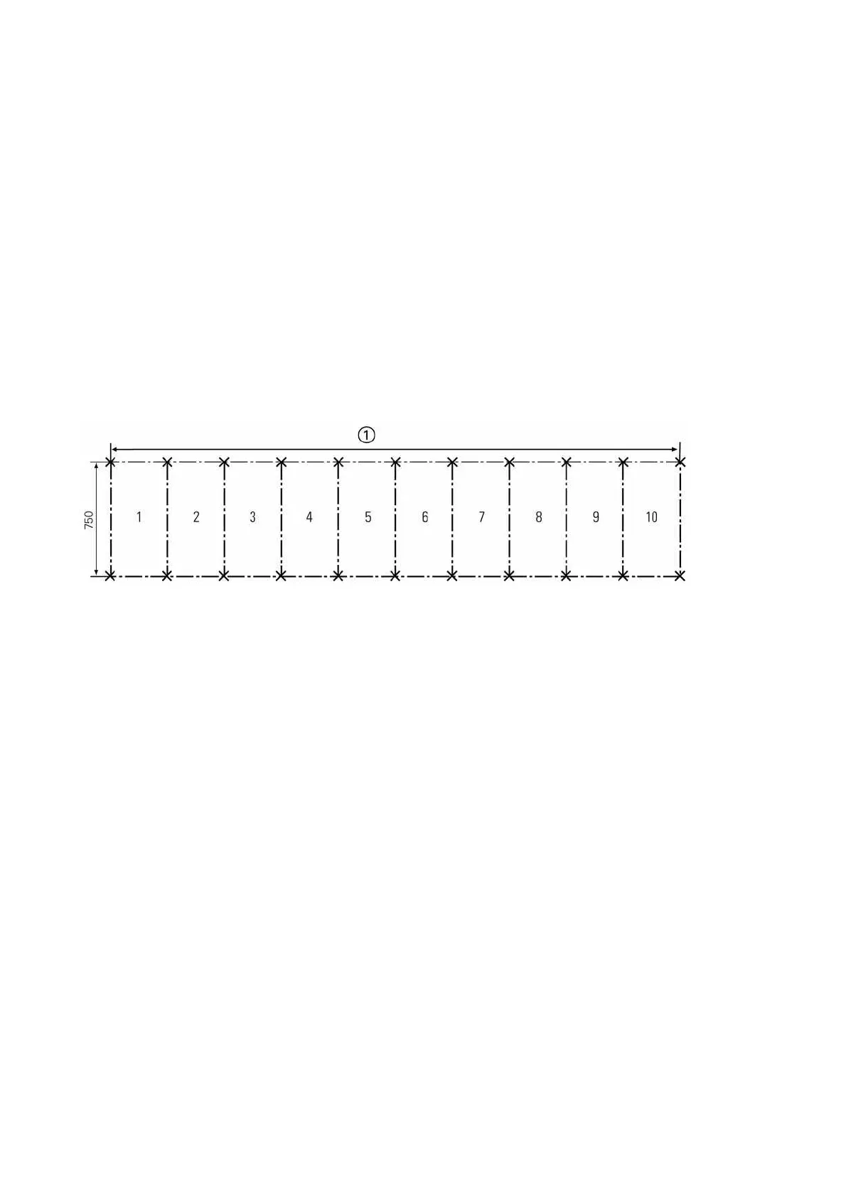
• Determine level differences between the installation surfaces of the panels using
a measuring sheet, and compensate them with shims.
Stipulations for evenness
and straightness
11.7 Comments on electromagnetic compatibility
To achieve appropriate electromagnetic compatibility (EMC), some basic requirements
must be observed while erecting the switchgear. This applies especially to the
installation and connection of external cables and wires.
Basic measures for ensuring EMC are already taken during design and assembly of
the switchgear panels. Among other things, these measures include:
• the low-voltage compartment is an integral part of the panel, which means that
the protection and control devices with the internal wiring are metal-enclosed;
• reliable earth connections of the frame parts via toothed contact washers or locking
washers;
• inside the panel, wires are laid in metal ducts;
• spatial separation of sensitive signal wires from wires with high interference voltage
levels;
• limitation of switching overvoltages of inductive loads (e.g. relay or contactor coils,
motors) by means of protective circuits with diode, varistor or RC element;
• within the LV compartment, the secondary devices are mounted in defined zones;
• shortest possible connection between corresponding modules in subracks;
• consideration of the magnetic leakage fields of conductor bars and cables;
• protection of subracks and wiring backplanes against interference by perforated
shielding plates;
• large surface bonding between all modules and devices as well as bonding to
the earthing conductor of the switchgear assembly.
Fig. 39: Measuring sheet for the foundation. Evenness/straightness tolerance according to DIN 43661:
1 mm per 1 m length, 2 mm for the total length.
a
Total
switchgear
width

 Loading...