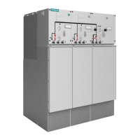
Installation
96 Revision 03 * INSTALLATION AND OPERATING INSTRUCTIONS 8DJH * 500-8067.9
Ö Remove the fixing bolts of the front plate.
Ö Remove the front plate of the switchgear to the front.
Ö If the low-voltage niche is used by the customer: Remove four Torx bolts size M6 of
the niche cover and remove the niche cover upwards.
Ö Following the circuit diagrams, connect the wires f to the terminal strip d or
directly to equipment terminals (e.g. CAPDIS S2+, short-circuit indicator),
and lay them cleanly. Cables are routed to the outside laterally (arrow) through
a cut-out stopper. Use the wiring duct
a as far as possible.
Ö Do not switch on auxiliary voltage yet.
13.4 Correcting circuit diagrams
Ö Note any modifications which may have been made during installation or
commissioning in the supplied circuit diagrams.
Ö Send the corrected documentation to the regional Siemens representative so that
the modifications can be included.
ATTENTION!
The transmission linkage of the ready-for-service indicator s must move freely.
Ö Lay the cables following the dotted line f.

 Loading...