:LULQJ
S7-300 Automation System, Hardware and Installation: CPU 31xC and CPU 31x
7-18 A5E00105492-03
,QVHUWLQJWKHEXVFRQQHFWRULQWRWKHPRGXOH
1. Insert the wired bus connector into the module.
2. Screw-tighten the bus connector on the module.
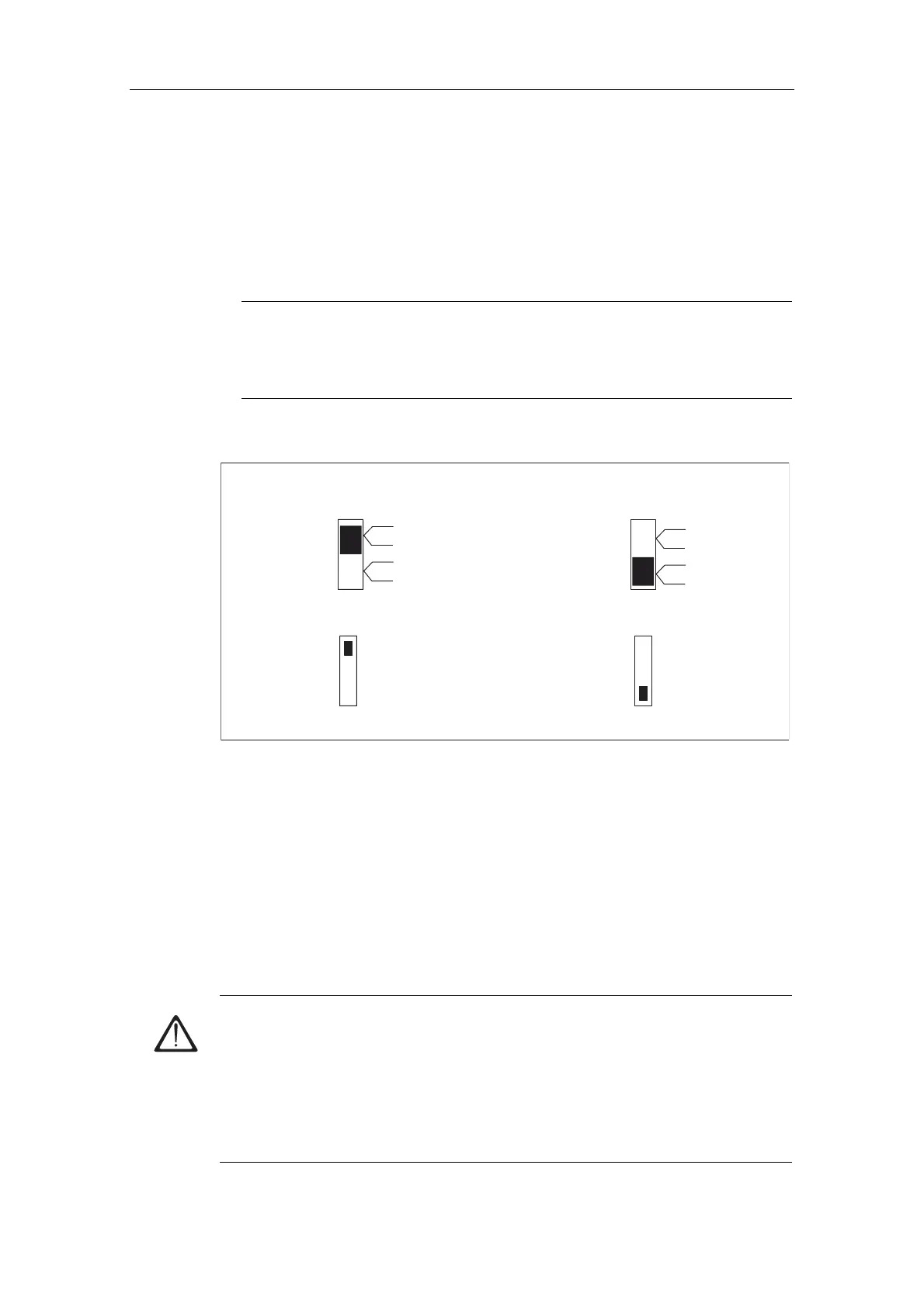
3. If the bus connector is at the start or end of a segment, you have to enable the
terminating resistor (Switch position "ON" see figure below)
1RWH
6ES7 972-0BA30-0XA0 bus connectors are not equipped with a terminating
resistor. You cannot connect it at the beginning or end of a segment.
Please make sure during start-up and normal operation that power is always
supplied to stations where the terminating resistor is active.
Terminating resistance switched on
Terminating resistance switched off
on
off
On
Off
on
off
On
Off
Figure 7-8 Bus connector: Enabled and disabled terminating resistor
5HPRYLQJEXVFRQQHFWRUV
With a looped-through bus cable, you can unplug the bus connector from the
PROFIBUS-DP interface at any time, without interrupting data communication on
the network.
3RVVLEOHGDWDWUDIILFHUURUV
:DUQLQJ
Data traffic error might occur on the bus!
A bus segment must always be terminated at both ends with the terminating
resistor. This, for example, is not the case if the last slave with bus connector is off
power. Since the bus connector draws its power from the station, the terminating
resistor has no effect.
Please make sure that power is always supplied to stations on which the
terminating resistor is active.
 Loading...


