&RQILJXULQJ
S7-300 Automation System, Hardware and Installation: CPU 31xC and CPU 31x
5-22 A5E00105492-03
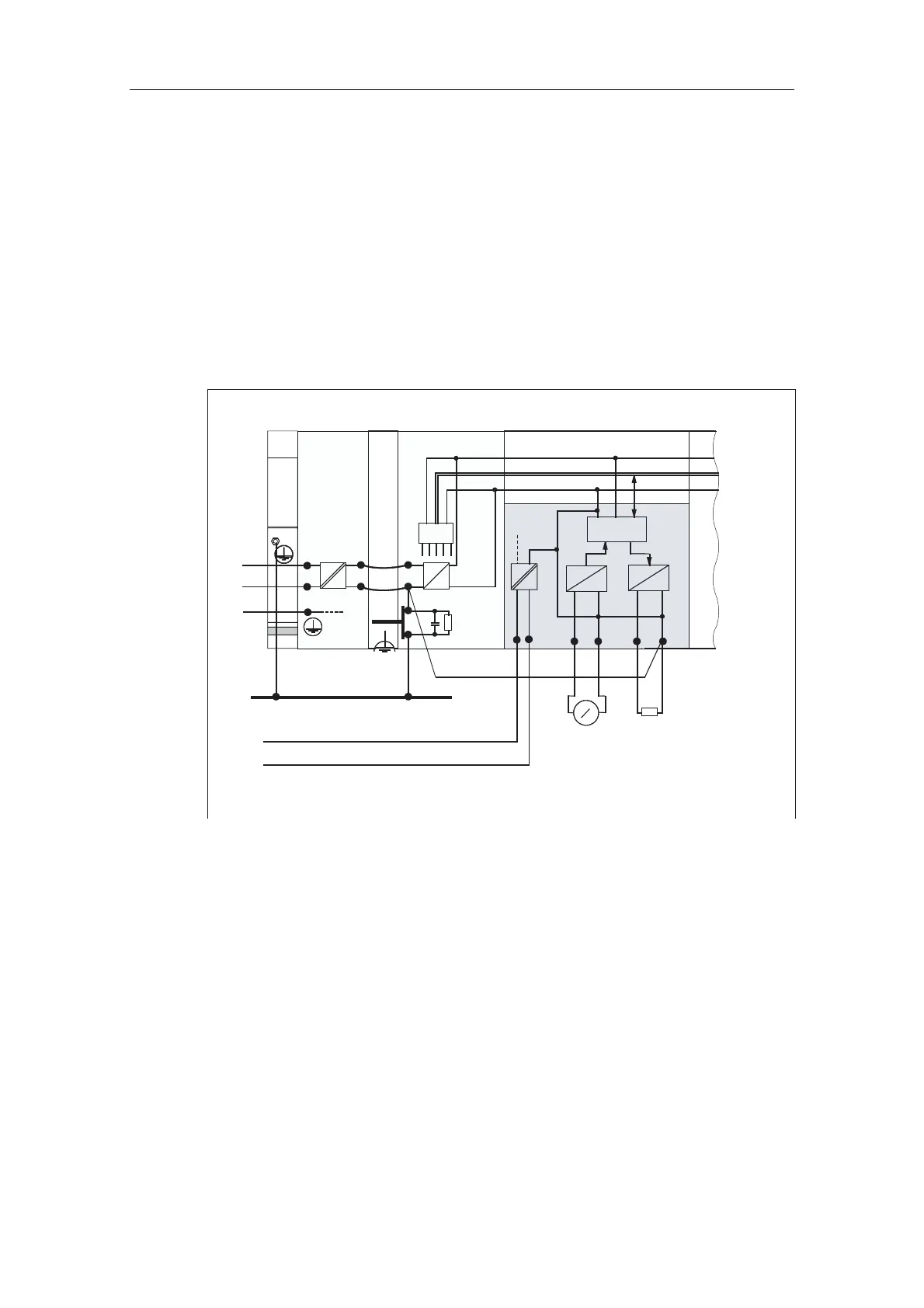
1RQLVRODWHGPRGXOHV
When non-isolated modules are installed, the reference potentials of the control
circuit (M
internal
) and analog circuit (M
analog
) are not electrically isolated.
([DPSOH
For operation with an SM 334 AI 4/AO 2 analog I/O module you must connect one
of the grounding terminals M
analog
to the CPU's chassis ground.
The figure below shows a sample configuration of an S7-300 CPU with non-
isolated modules.
L+
N
M
L1
L+
M
PS
S7-300 CPU
µ
P
L1
N
U
internal
M
internal
Data
4AI/2AO
PE
1 mm
2
M
analog
M
external
V
A
++
D
A
A
D
Ground bus
in cabinet
DC 24 V load power supply
Figure 5-10 Configuration with non-isolated modules
 Loading...


