7HVWLQJ)XQFWLRQV'LDJQRVWLFVDQG)DXOW(OLPLQDWLRQ
S7-300 Automation System, Hardware and Installation: CPU 31xC and CPU 31x
A5E00105492-03
11-29
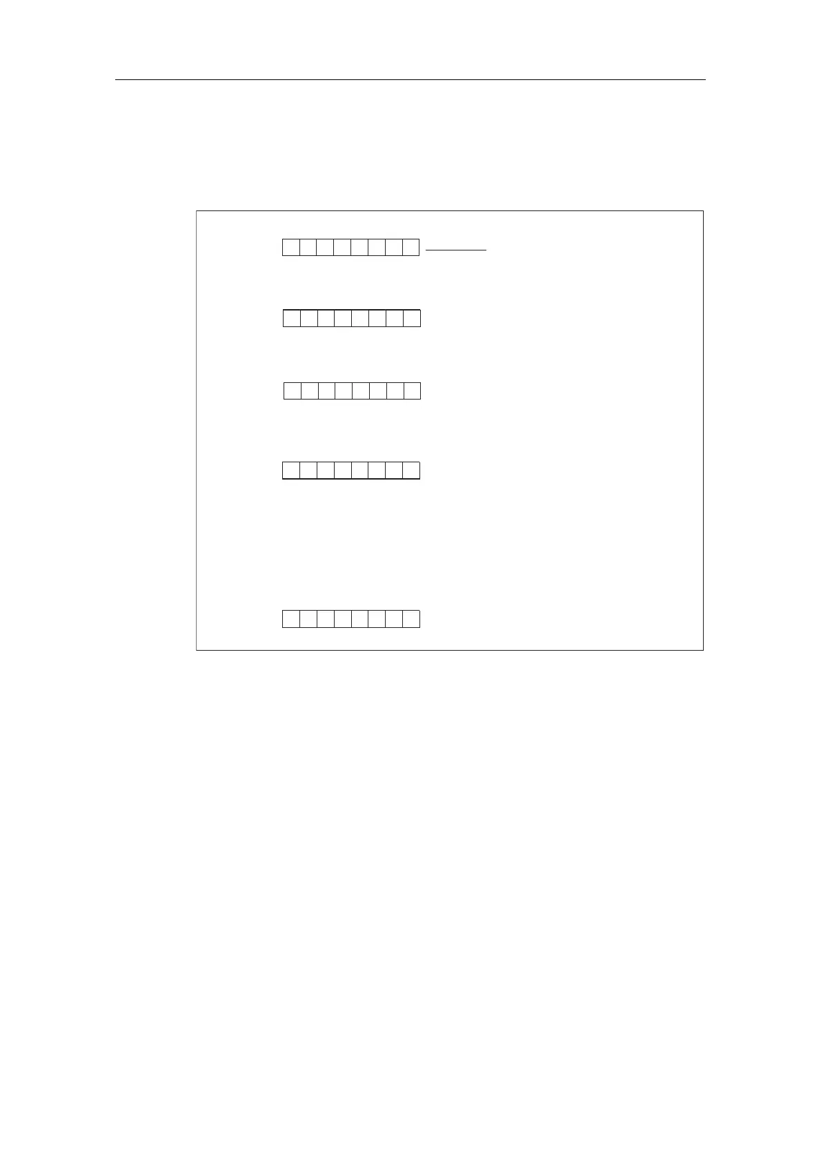
6WUXFWXUHRIWKHLQWHUUXSWGDWDZKHQDGLDJQRVWLFLQWHUUXSWLVJHQHUDWHGE\6)%
RQWKHLQWHOOLJHQWVODYHDIWHUE\WH\
Byte y +7
0: Module o.k.
1: Module fault
Byte y +6
Byte y +5
Byte y +4
7 6543210Bit no.
0
Note the SFB 75 usage description
Note that this diagnostic data has a
fixed meaning in the S7 context.
You will find more information in the
STEP 7 Online Help or in the
Reference Manual System Software
for S7-300/400 System and Standard
Functions in the Diagnostic Data
chapter.
7 6543210Bit no.
7 6543210Bit no.
7 6543210Bit no.
Byte y +19
7 6543210Bit no.
.
.
.
Figure 11-11 Bytes y+4 to y+7 for the diagnostic interrupt (SFB 75)
 Loading...


