$SSHQGL[
S7-300 Automation System, Hardware and Installation: CPU 31xC and CPU 31x
12-14 A5E00105492-03
(TXLSRWHQWLDOERQGLQJFRQGXFWRU
To reduce potential differences and ensure proper functioning of your electronic
equipment, you must install equipotential bonding conductors.
Note the following points on the use of equipotential bonding conductors:
• The lower the impedance of an equipotential bonding conductor, the more
effective is equipotential bonding.
• When shielded signal cables interconnect two system components and the
shielding is connected on both ends to ground/protective conductors, the
impedance of the additional equipotential bonding conductor must not exceed
10% of the shielding impedance.
• Determine the cross-section of your equipotential bonding conductor on the
basis of the maximum equalizing current that will flow through it. The
equipotential bonding conductor cross-section that has proven best in practice
is 16 mm
2
.
• Always use equipotential bonding conductors made of copper or galvanized
steel. Always connect the cables on a large surface to the equipotential
busbar/protective conductor and protect it against corrosion.
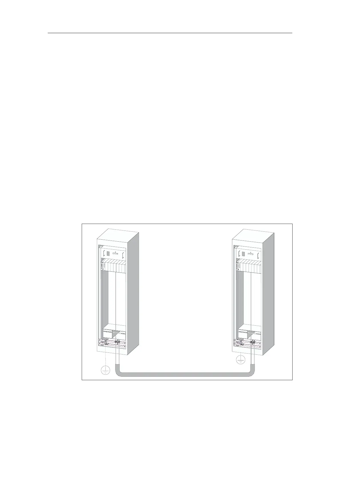
• Route your equipotential bonding conductor to minimize the area between the
equipotential bonding conductor and signal lines as far as possible (see the
figure below).
Figure 12-5 Equipotential bonding
 Loading...


