:LULQJ
S7-300 Automation System, Hardware and Installation: CPU 31xC and CPU 31x
A5E00105492-03
7-3
%ULHIRYHUYLHZRIIURQWFRQQHFWRUV
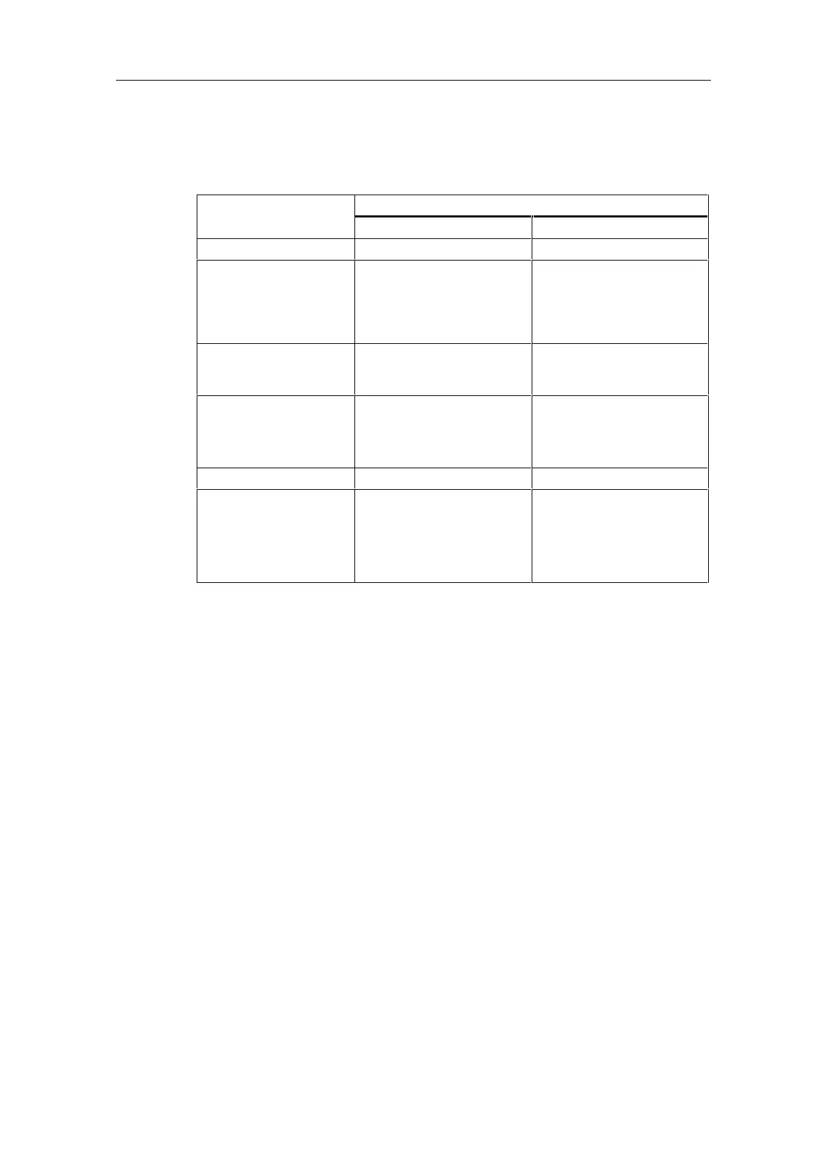
Table 7-3 Wiring conditions for front connectors
)URQWFRQQHFWRU
&RQQHFWDEOHFDEOHV
20-pin 40-pin
solid conductors No No
flexible conductors
• Without wire end
ferrule
• With wire end ferrule
0.25 mm
2
to 1.5 mm
2
0.25 mm
2
to 1.5 mm
2
0.25 mm
2
to 0.75 mm
2
0.25 mm
2
to 0.75 mm
2
• Potential supply: 1.5 mm
2
Number of conductors per
terminal
1 conductor, or 2 conductors
up to 1.5 mm
2
(total) in a
common wire end ferrule
1 conductor, or 2 conductors
up to 0.75 mm
2
(total) in a
common wire end ferrule
Diameter of the conductor
insulation
max. 3.1 mm • max. 2.0 mm for
40 conductors
• max. 3.1 mm for 20
conductors
Stripped length 6 mm 6 mm
Wire end ferrules to DIN
46228
• Without insulating
collar
• With insulating collar
Version A, 5 mm to 7 mm
length
Version E, up to 6 mm long
Version A, 5 mm to 7 mm
length
Version E, up to 6 mm long
 Loading...


