18/93
Building Technologies Division User Manual RWF55... CC1U7867en
Infrastructure & Cities Sector 4 Electrical connections 05.11.2013
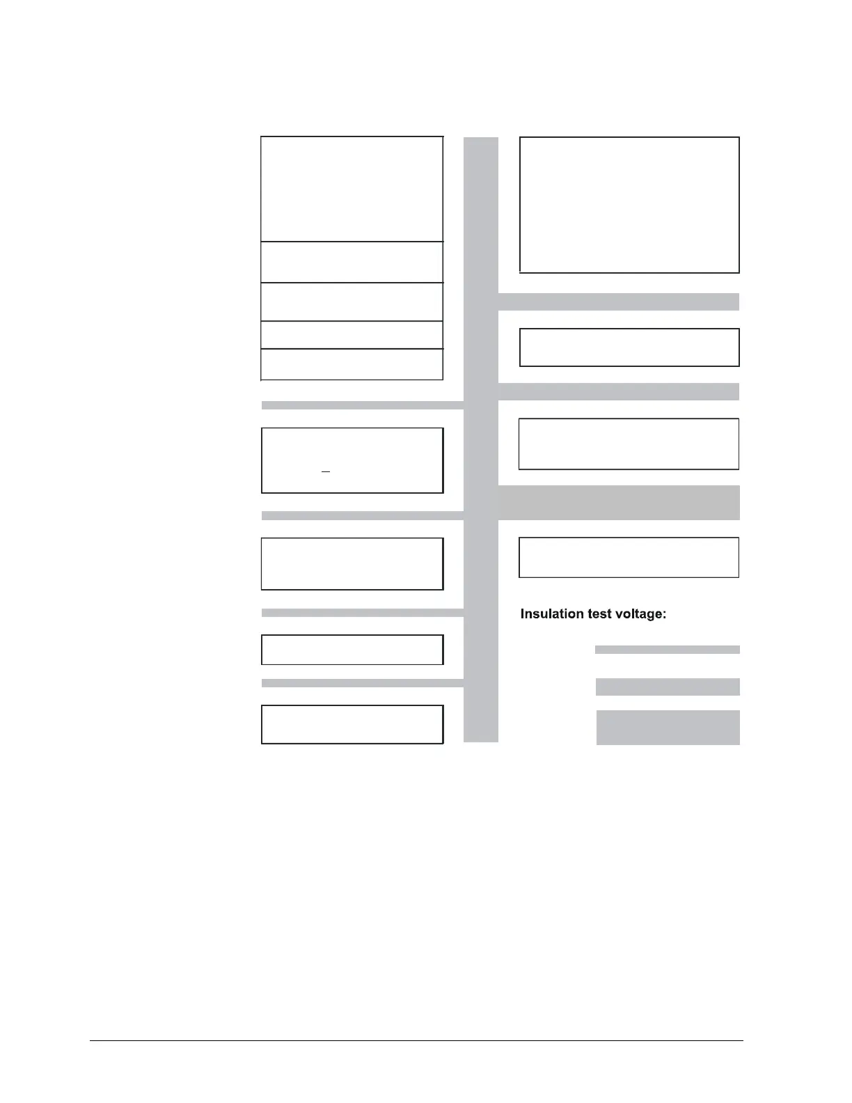
4.2 Galvanic separation
The illustration shows the maximum test voltages between the electrical circuits.
ir damper control
3-position output
K2, K3, KQ
- Relay K2 (NO contact):
Controlling element open
- Relay K3 (NO contact):
Controlling element closed
DC 50 V
AC 2210 V
AC 3510 V
Analo
input
Analo
input
Analo
input
InP1
InP2
InP3
For resistance thermometer,
thermo elements
or standard signals
D1, D2, DG
For potentialfree contacts
USB setup
For PC-software ACS411
Binary input
interface
LED
Buttons
Power supply measuring
transducer
G+, G-
DC 24 V 10%, max. 30 mA
(short-circuit proof)
+
Burner release
1P, 1N
Relay (NO contact)
Power consumption
max. 20 VA at
+10%/-15%, 48...63 Hz
AC 110...240 V,
7867d02e/071
RS-485
Modbus Slave
A+, A-
Analo
output
Only RWF55.6
Profibus DP
Multifunctional rela
6N, 6P
Relay K6
Figure 4: Test voltages
 Loading...


