64/93
Building Technologies Division User Manual RWF55... CC1U7867en
Infrastructure & Cities Sector 9 Self-setting function 05.11.2013
9.2 Checking the controller parameters
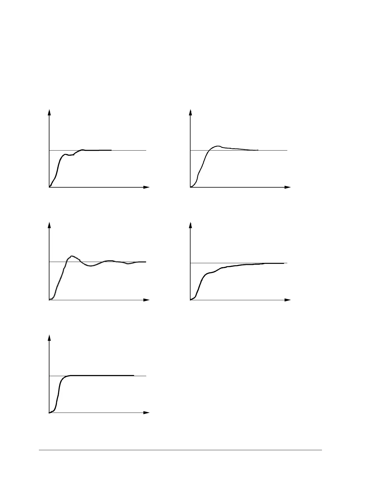
Optimum adjustment of the controller to the controlled system can be checked by
recording a startup sequence with the control loop closed. The following diagrams
indicate possible incorrect adjustments, and their correction.
The response to a setpoint change is shown here for a 3rd order controlled system for
a PID controller. The method used for adjusting the controller parameters can,
however, also be applied to other controlled systems. A suitable value for dt is rt/4.
Pb too small Pb too large
t
x
w
7865d17/1099
Figure 33: Pb too small
t
x
w
7865d15/1099
Figure 34: Pb too large
rt, dt too small rt, dt too large
t
x
w
7865d16/1099
Figure 35: rt, dt too small
t
x
w
7865d14/1099
Figure 36: rt, dt too large
Optimum adjustment
t
x
w
7865d18/1099
Figure 37: Optimum adjustment
Example
 Loading...


