33/93
Building Technologies Division User Manual RWF55... CC1U7867en
Infrastructure & Cities Sector 5 Operating modes 05.11.2013
5.5 Weather-compensated setpoint shifting
The RWF55 can be configured so that weather-compensated setpoint shifting is
activated when an LG-Ni1000 outside sensor or a Pt1000 is connected.
Reference!
See chapter 8.3 Analog input InP3
To take into account the time response of a building, weather-compensated setpoint
shifting uses the attenuated outside temperature rather than the current outside
temperature.
This attenuated outside temperature is determined on the basis of the current outside
temperature and a filter constant. With the RWF55, this filter value (parameter dF3) can
be adjusted. In the event of a power failure, this filter is reset. The minimum and
maximum setpoints can be set using the lower setpoint limit SPL and the upper setpoint
limit SPH.
The system also prevents the lower working range limit oLLo and upper working range
limit oLHi from exceeding/dropping below the system temperature limits.
Note!
Each RWF55 must have its own separate outside sensor (no parallel connection).
This function has been optimized for heating systems with DHW.
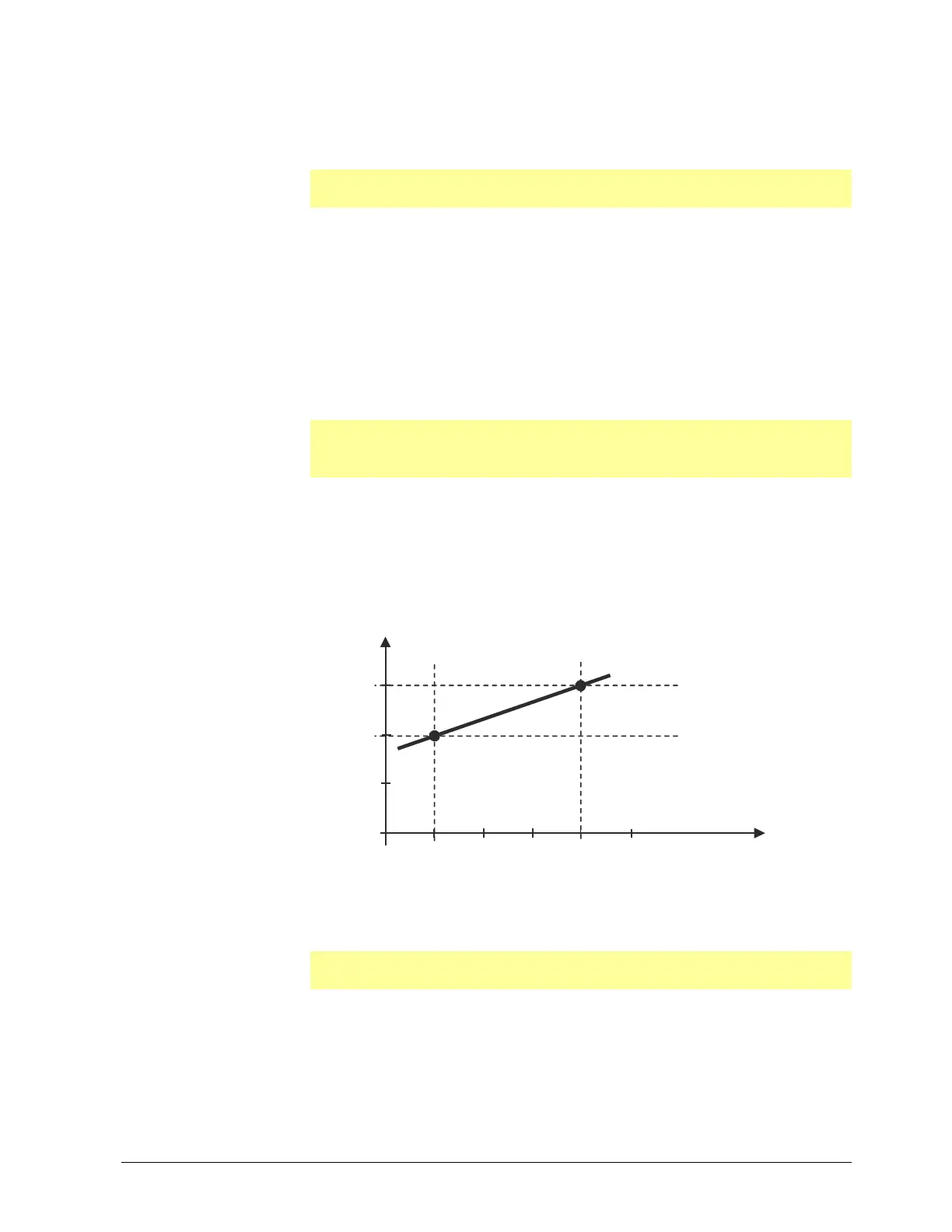
The heating curve describes the relationship between the boiler temperature setpoint
and the outside temperature. It is defined by 2 curve points. For 2 outside
temperatures, the user defines the boiler temperature setpoint that is required in each
case. The heating curve for the weather-compensated setpoint is calculated on this
basis. The effective boiler temperature setpoint is limited by the upper setpoint limit SPH
and the lower setpoint limit SPL.
Setpoint (°C)
Ht1
Ht2
+60
+50
+20
10
0
-10
Outside temperature (°C)
At2 At1
7867d03e/0712
Figure 16: Heating curve slope
The two curve points are set at the parameter level.
Reference!
See chapter 7 Parameterization PArA
Heating curve
 Loading...


