19/93
Building Technologies Division User Manual RWF55... CC1U7867en
Infrastructure & Cities Sector 4 Electrical connections 05.11.2013
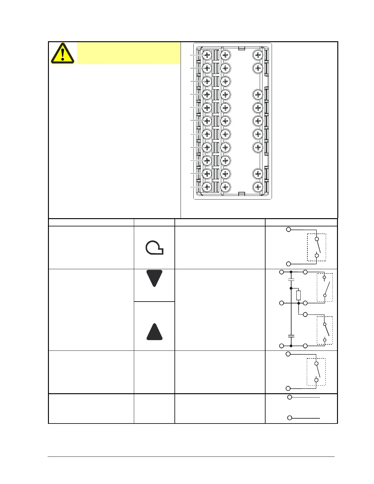
4.3 Assignment of terminals
Caution!
Electrical connections must always be
made by qualified personnel!
11
12
13
14
21
22
23
31
32
+
-
C1
C2
C3
C4
R+
R-
G+
G-
D1
D2
DG
6N
6P
K3
KQ
K2
1P
1N
N
L1
7867z01/0712
Figure 5: Assignment of terminals
Outputs Display LED Terminal no. Connection diagram
Relay Burner release:
Relay K1: 1P, 1N
1P pole
1N NO contact
1P
P
S
1N
7866a01/0911
3-position output:
Relay K3: Controlling element
CLOSE
Relay K2: Controlling element
OPEN
K3 NO contact
KQ common pole
K2 NO contact
P
S
K3
KQ
K2
S
P
7866a02/0911
Multifunctional relay K6: 6N, 6P
K6
6N NO contact
6P pole
6N
S
P
6P
7867a12/0712
Analog output A+, A-
DC 0(4)...20 mA, DC 0...10 V
A+
A-
+
A-
+
-
7866a03/0911
 Loading...


