38/93
Building Technologies Division User Manual RWF55... CC1U7867en
Infrastructure & Cities Sector 6 Operation 05.11.2013
6 Operation
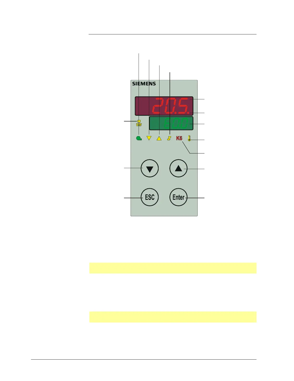
6.1 Meaning of display and buttons
RWF55.X
ctual value display (red)
and parameter value
USB-LED
Setpoint display (green)
and parameter symbol
Enter button
Increase value
ESC button
Decrease value
7867z03e/1012
Operating mode 2-stage
Controlling element OPEN/stage 2
Controlling element CLOSED/stage 1
Burner release
Thermal shock protection
Alarm function
Communication
via interface
Figure 20: Meaning of display and buttons
The two 7-segment displays (red and green) show hyphens and all LEDs light up for
about 5 seconds.
The upper display (red) shows the actual value.
The lower display (green) shows the setpoint.
Reference!
See chapter 8.9 Display diSP.
When entering parameters, the parameter symbol (green) and the set value (red)
appear.
The actual value is shown on the actual value display (red) and tUnE flashes on the
setpoint display (green).
Reference!
See chapter 9.1 Self-setting function in the high-fire operation.
Initialization
Basic display
Parameter display
Self-setting function
 Loading...


