EasyManuals Logo
Home>Siemens>Servo Drives>SIMOTICS S-1FL6

Siemens SIMOTICS S-1FL6 Compact Operating Instructions

Siemens SIMOTICS S-1FL6
118 pages
To Next Page IconTo Next Page
To Previous Page IconTo Previous Page
Page #48 background imageLoading...
Page #48 background image
Getting Started
48 A5E37208904-003, 04/2017
4.3
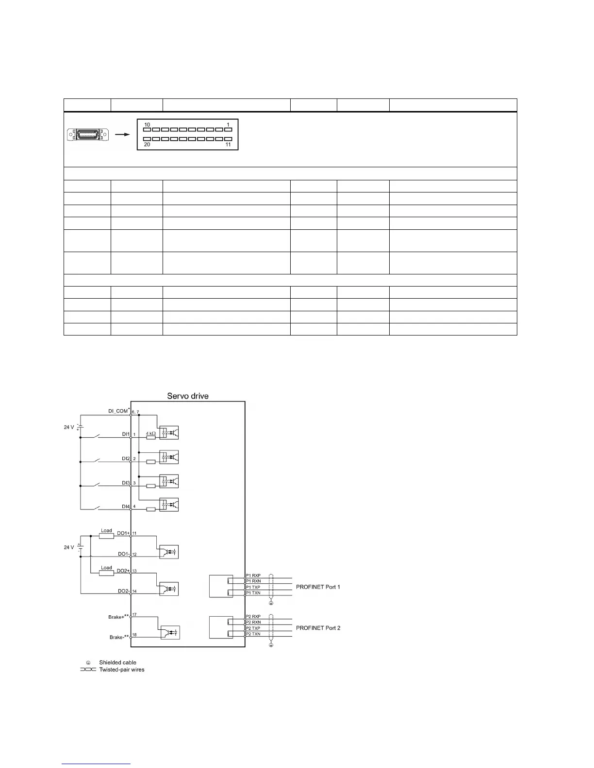
Control/Status interface - X8
4.3.1
Interface definition
Pin
Signal
Description
Pin
Signal
Description
Type: 20-pin MDR socket
Digital inputs/outputs
1
DI1
Digital input 1
11
DO1+
Digital output 1, positive
2
DI2
Digital input 2
12
DO1-
Digital output 1, negative
3
DI3
Digital input 3
13
DO2+
Digital output 2, positive
4
DI4
Digital input 4
14
DO2-
Digital output 2, negative
6
DI_COM
Common terminal for digital
inputs
17
*
BK+
Motor holding brake control sig-
nal, positive
7
DI_COM
Common terminal for digital
inputs
18
*
BK-
Motor holding brake control sig-
nal, negative
None
5
-
Reserved
15
-
Reserved
8
-
Reserved
16
-
Reserved
9
-
Reserved
19
-
Reserved
10
-
Reserved
20
-
Reserved
* The pins are used to connect the brake control signals for 200 V variant drive only.
4.3.2
Standard wiring
Example 1

Other manuals for Siemens SIMOTICS S-1FL6

Questions and Answers:

Question and Answer IconNeed help?

Do you have a question about the Siemens SIMOTICS S-1FL6 and is the answer not in the manual?

Siemens SIMOTICS S-1FL6 Specifications

General IconGeneral
BrandSiemens
ModelSIMOTICS S-1FL6
CategoryServo Drives
LanguageEnglish

Related product manuals