Getting Started
A5E37208904-003, 04/2017
49
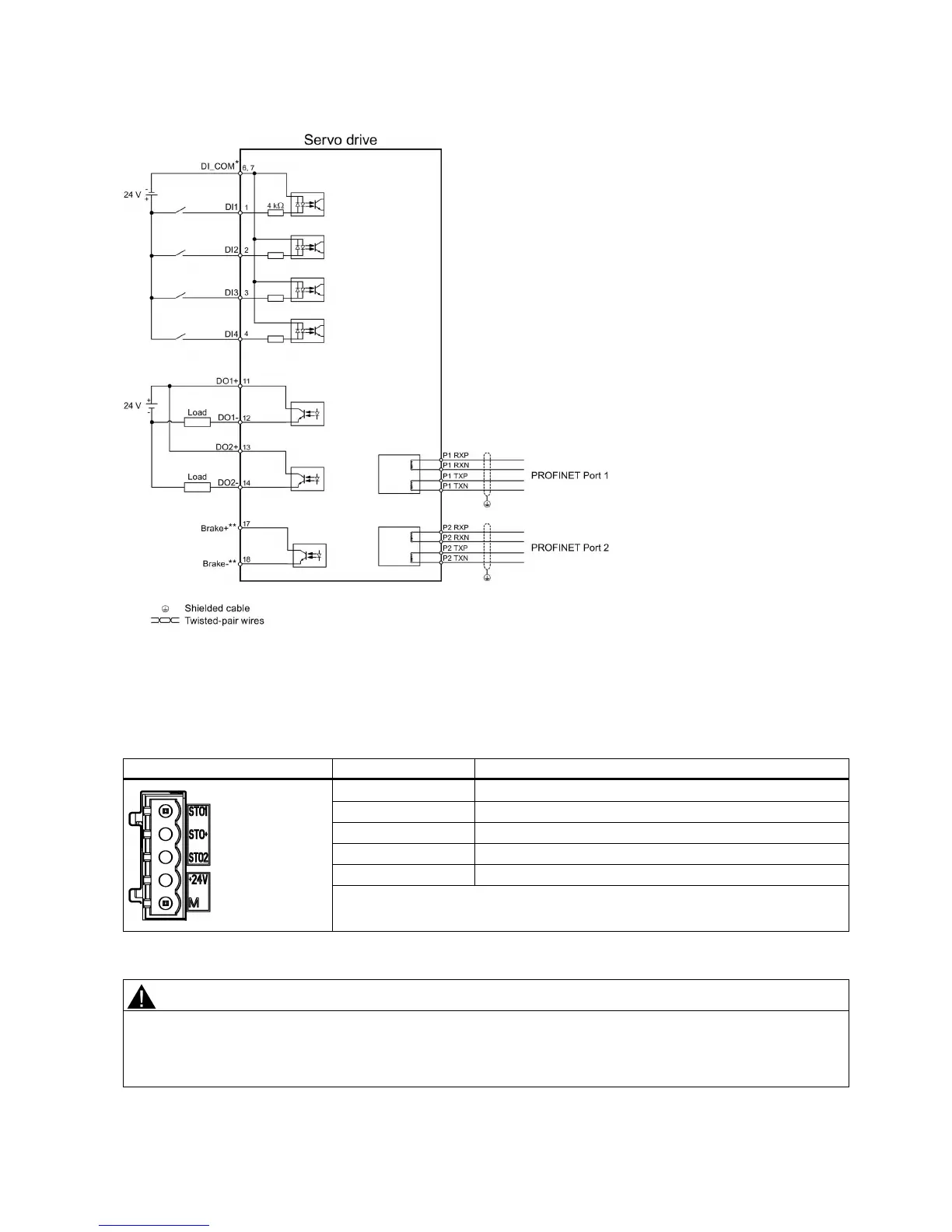
Digital inputs, supporting both PNP and NPN types.
The pins are used to connect the brake control signals for 200
V variant drive only. Refer to the section "Motor holding
brake" in SINAMICS V90, SI
MOTICS S-1FL6 Operating Instructions for the detailed connections.
The pin assignment for the 24 V power supply/STO interface is shown as follows:
Safe torque off channel 1
Specific power supply for safe torque off
Safe torque off channel 2
Maximum conductor cross-section: 1.5 mm
2
Material damages and personal injuries by the drop of a hanging axis
When the servo system is used as a hanging axis, the axis will drop if the positive and negative poles of the 24 V power
supply are connected inversely. Unexpected drop of the hanging axis may cause material damages and personal injuries.
Make sure that the 24 V power supply is correctly connected.

 Loading...


