Operator control (hardware)
2.3 Error and status displays
SIMOTION D410-2
32 Manual, 02/2012
2.3 Error and status displays
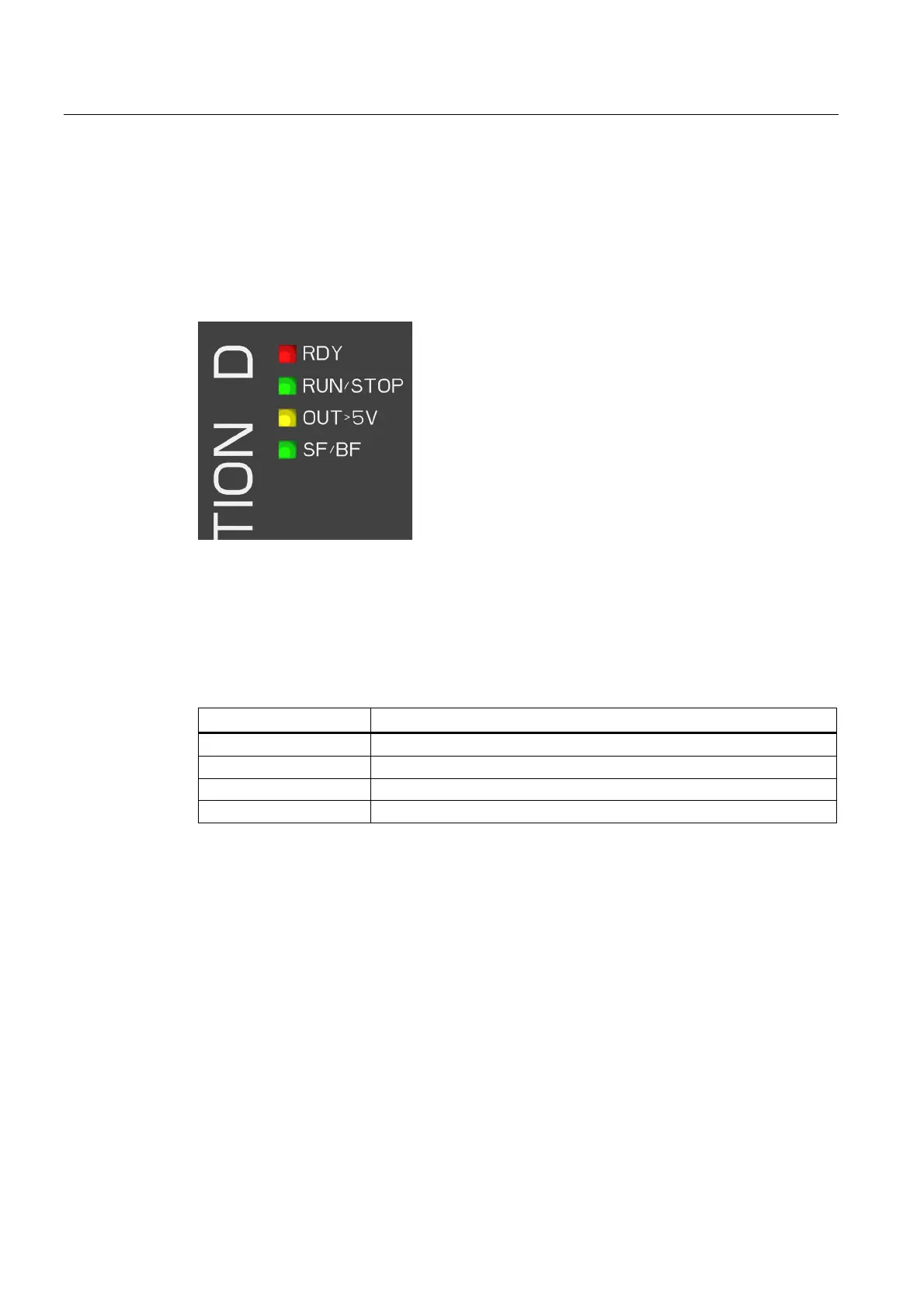
Arrangement of LED displays
The LED displays are located next to the CompactFlash card plug-in slot on the
SIMOTION D410-2.
Figure 2-7 LED displays
Meaning of the LED displays
This table describes the LEDs and their meaning.
Table 2- 4 Error and status displays
LED Meaning
RDY Status indicator of the SINAMICS Integrated
RUN/STOP SIMOTION D410-2 operating states
OUT>5V Encoder current supply > 5 V (TTL/HTL)
SF/BF: Group error / bus fault
Additional information
You can perform a detailed diagnosis with a PG/PC and the engineering system. For
information about diagnostics using LED displays, refer to the
SIMOTION D410-2
Commissioning and Hardware Installation Manual.

 Loading...


