Interfaces
3.5 Digital I/Os / temperature sensor / analog input
SIMOTION D410-2
42 Manual, 02/2012
3.5.2 Interface characteristics
Table 3- 12 Interface characteristics
Characteristics Type
Connector type (X120, X121) 12-pin spring-loaded terminal
Connector type (X130, X131) 8-pin spring-loaded terminal
Connectable conductor cross-sections
• Flexible
• Flexible, with wire-end ferrule without plastic sleeve
• Flexible, with wire-end ferrule with plastic sleeve
• 0.14 mm² to 1.5 mm²
• 0.25 mm² to 1.5 mm²
• 0.25 mm² to 0.5 mm²
Stripped length 9 mm
Tool Screwdriver 0.4 x 2.0 mm
Max. cable length 30 m
Note
To prevent an incorrect connection, the X120, X121, X130 and X131 connectors are
supplied coded. The terminal and pin numbers are also inscribed on the connectors.
3.5.3 Interface assignment
The following tables contain the pin assignments of the onboard I/Os.
X120
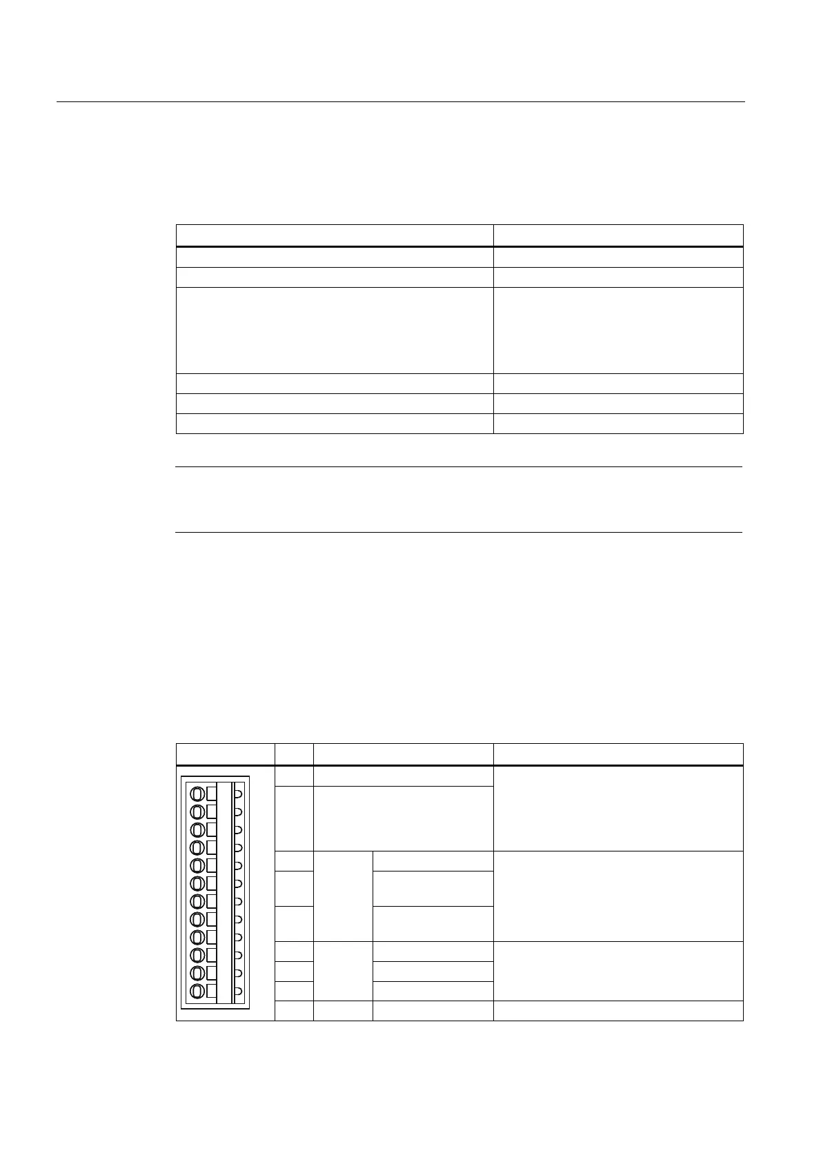
Table 3- 13 Interface assignment X120
Representation Pin Designation Information
1 +Temp
2 -Temp
Motor temperature sensor input.
Temperature sensors: KTY84–1C130 /
PTC
Measuring current via temperature sensor
connection: 2 mA
3 DI 16
4 DI 17+ / EP +24 V3
(Enable Pulses)
5
F-DI 0
2)
DI 17- / EP M3
(Enable Pulses)
1)
Fail-safe digital input 0 or digital inputs 16
and 17
EP function (Enable Pulses) when using
Safety Integrated basic functions via
terminal
6 DI 18
7 DI 19+
8
F-DI 1
2)
DI 19-
1)
Fail-safe digital input 1 or digital inputs 18
and 19
9 F-DI 2
2)
DI 20 Fail-safe digital input 2 or digital inputs 20

 Loading...


