Mounting and Commissioning
3.1 Mounting and Connections
SIPROTEC, 7RW80, Manual
C53000-G1140-C233-1, Release date 10.2010
150
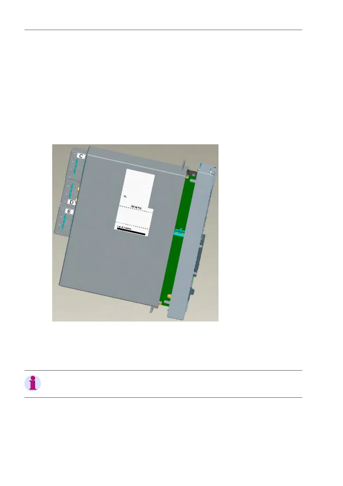
3.1.2.4 Reassembly
The reassembly of the device is performed in the following steps:
Carefully insert the complete electronics block into the housing. Please observe the following:
The connections of the communication modules point at the bottom of the housing.
Insert the electronics block into the housing, until the supporting part rests against the front edge of the hous-
ing. Press the left housing wall slightly out and insert the electronics block carefully further into the housing.
When the front edge of the housing and the inside of the front plate touch, center the front plate by carful lateral
movements. This makes sure that the front plate encloses/surrounds the housing. The electronics block can
only be inserted centered up to the end stop.
Figure 3-8 Reassembly of Device
Fix the front cover to the housing with the two medium screws at the top and bottom of the front cover. The two
covers can be inserted again either now or after the reinstallation of the device. Now install the device in accor-
dance with the Sections Panel Flush Mounting, Panel Surface Mounting or Cubicle Mounting.
Note
Insert the voltage terminal blocks again and lock them in place!
 Loading...


