Mounting and Commissioning
3.1 Mounting and Connections
SIPROTEC, 7RW80, Manual
C53000-G1140-C233-1, Release date 10.2010
154
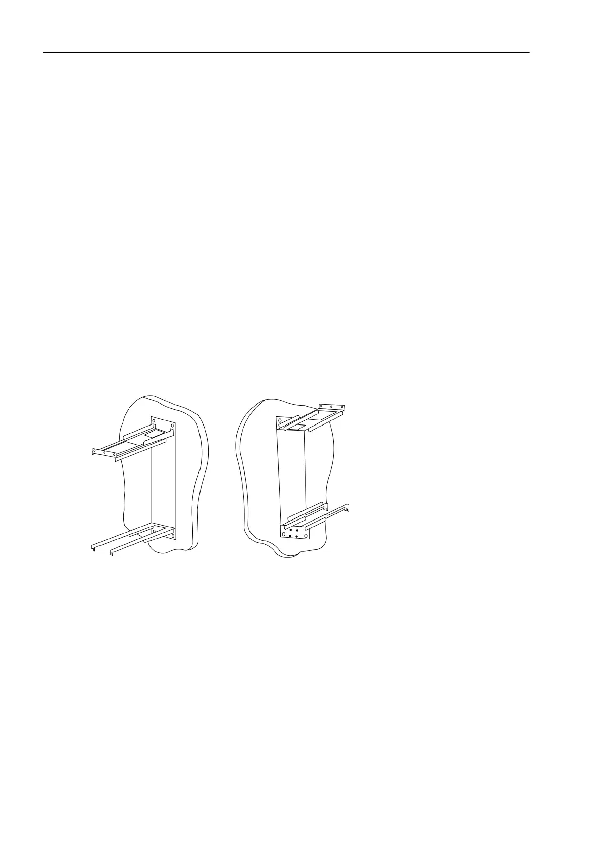
3.1.3.4 Panel Surface Mounting
When ordering the device as surface-mounting case (9th digit of the ordering number= B), the mounting frame
shown below is part of the scope of delivery.
For installation, proceed as follows:
• Drill the holes for the mounting frame into the control panel.
• Fasten the mounting frame with 4 screws to the control panel (the continuously open side of the mounting
frame is intended for the cable harnesses and can point at the top or bottom according to customer specifi-
cation).
• For wiring please remove the terminal block, wire the terminals and snap them back into place.
• Connect a solid low-ohmic protective and operational ground to the grounding terminal of the device. The
cross-section of the cable used must correspond to the maximum connected cross-section but must be at
least 2.5 mm
2
.
• Connections are realized via the screw terminals on the rear side of the device according to the circuit dia-
gram. The details on the connection technique for the communication modules on the bottom of the device
(port A and port B) in accordance with the SIPROTEC 4 System Description and the details on the connec-
tion technique for the voltage terminals on the back of the device in the Sections „Connections of the Voltage
Terminals“ must be observed.
• Insert the device into the mounting frame (make sure that no cables are jammed).
• Secure the device to the mounting frame with 4 screws. For dimensional drawings, refer to the Technical
Data, Section 4.12.
Figure 3-13 Mounting rails for panel surface mounting
 Loading...


