Mounting and Commissioning
3.1 Mounting and Connections
SIPROTEC, 7RW80, Manual
C53000-G1140-C233-1, Release date 10.2010
152
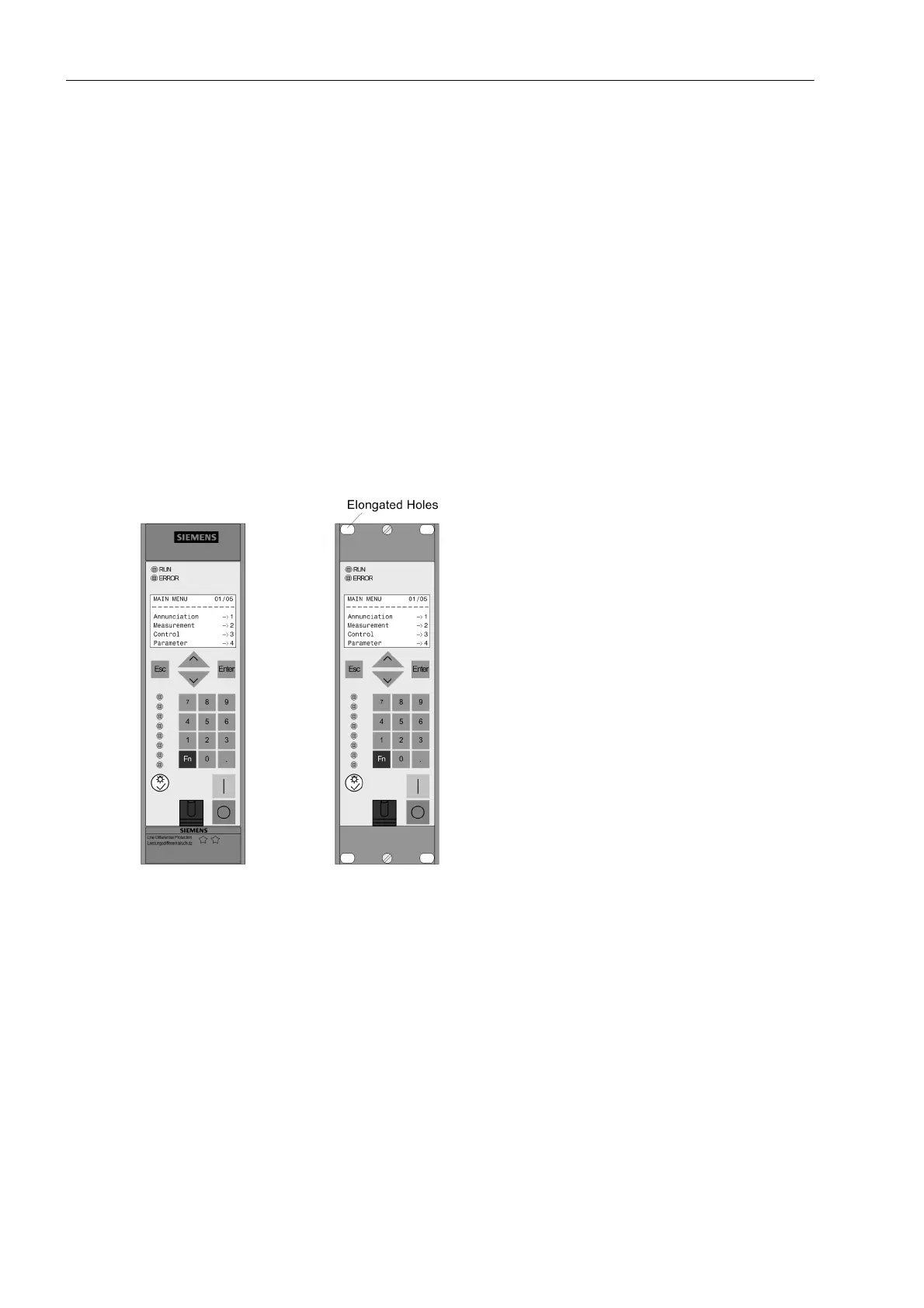
3.1.3.2 Panel Flush Mounting
The housing (housing size
1
/
6
) has 2 covers and 4 fixing holes.
• Remove the 2 covers at the top and bottom of the front cover. Thus, 4 elongated holes are revealed in the
mounting bracket and can be accessed.
• Insert the device into the panel cut-out and fasten it with four screws. For dimensional drawings, refer to
Section 4.12.
• Mount the 2 covers again.
• Connect a solid low-ohmic protective and operational ground to the grounding terminal of the device. The
cross-section of the cable used must correspond to the maximum connected cross-section but must be at
least 2.5 mm
2
.
• Connections are realized via the screw terminals on the rear side of the device according to the circuit dia-
gram. The details on the connection technique for the communication modules on the bottom of the device
(port A and port B) in accordance with the SIPROTEC 4 System Description and the details on the connec-
tion technique for the voltage terminals on the back of the device in the Sections „Connections of the Voltage
Terminals“ must be observed.
Figure 3-11 Panel flush mounting of a 7RW80
 Loading...


