6-31
6 General Repair
6B Hand Controls Repair
Figure B–28. Remove hitch pin clip and flat washer
(Single arm model shown)
DOUBLE CABLE MANUAL LIFT LEVER REMOVAL
The entire lift lever assembly may be easily removed
from the unit for bench inspection and repair:
1. If desired, remove the mower deck from the unit (see
Mower Deck repair section for specific instructions re-
garding mower deck removal if necessary), or:
2. Remove two 5/16-18 x 1-1/4" capscrews, locknuts
and spacers (T, I, & J, Figure B–27) that secure the
lift lever assembly to right side of the unit's frame.
Slide the lift guide bracket (H) up and out of position
between the frame and the lift lever mounting brack-
et.
3. Remove the hitch pin clip (O), and flat washer (N)
from lift lever arm shaft at left side of unit.
4. Slide the lift lever assembly straight out of lift pivot
bracket (M) and out of engagement with pins in un-
derside of lift mounting bracket assembly (L).
5. The lift lever assembly may now be moved to a work-
bench for additional inspection and any required ser-
vicing.
6. Visually inspect all parts for wear, corrosion, or dam-
age, and replace as necessary. Reassemble parts in
reverse order of disassembly.
DOUBLE CABLE MANUAL LIFT
TUBE ASSEMBLY REPLACEMENT
1. The lift tube assembly slides over the lift lever assem-
bly shaft, and can be removed by simply sliding the
lift tube away from the mounting bracket portion of
the lift lever assembly (Figure B–27).
2. Check the lift tube assembly for signs of wear, corro-
sion, or other damage, and replace as required.
3. Reassemble parts in reverse order of disassembly.
LIFT CABLE PULLEY REPLACEMENT
The right and left lift cable pulley assemblies are assem-
bled to the sides of the frame, and are accessible
through the rear wheel wells.
1. Remove the hex head capscrew and flange lock hex
nut that secure the pulley, pulley guard, and spacers
to the frame (AA-DD, Figure B–27).
2. Inspect parts for signs of wear or damage, and re-
place as required.
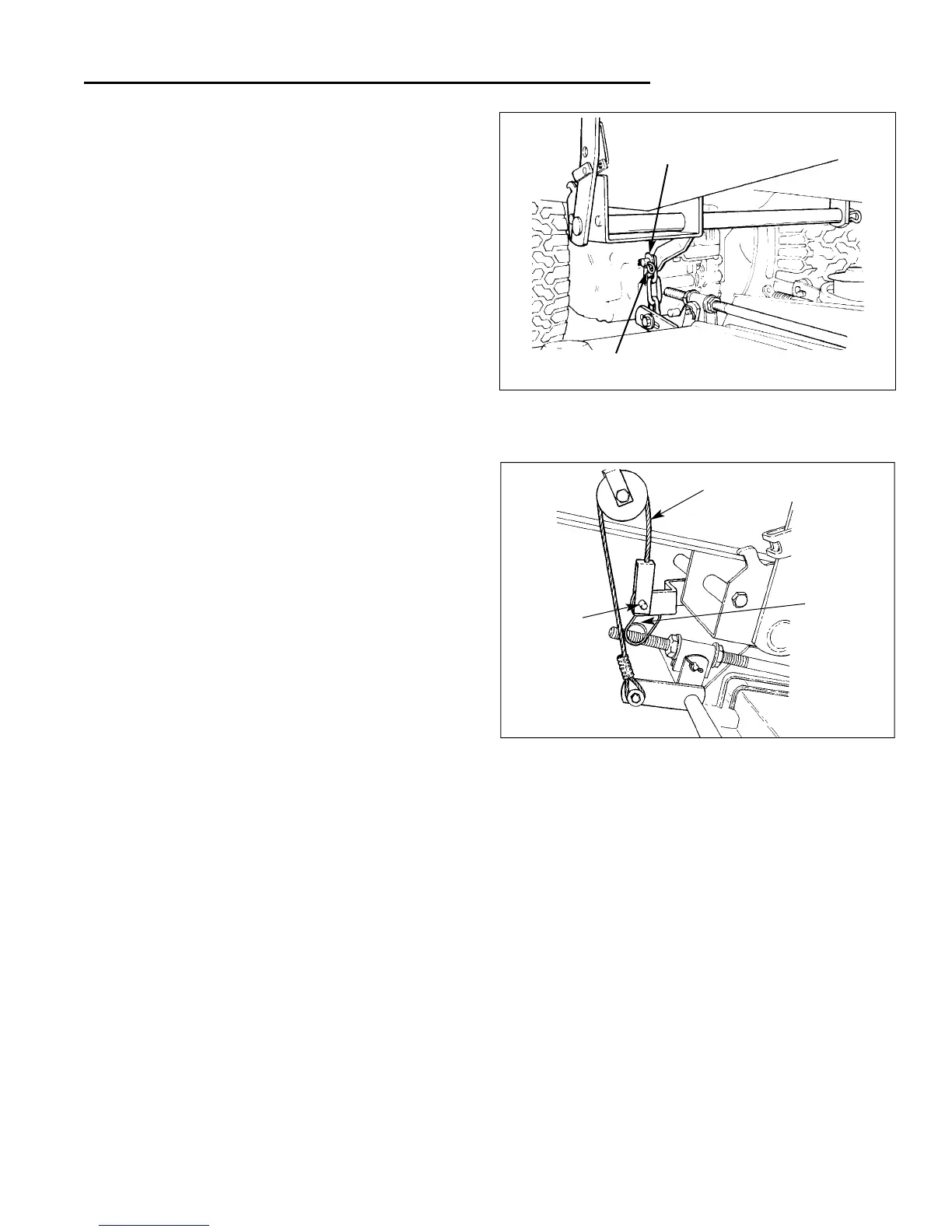
Figure B–29. Remove Pin and Clip (Double lift arm
model shown)
Hitch Pin
Flat Washer
Lift Cable Assembly
Pin
Clip
3. Reassemble parts in reverse order of disassembly,
making sure the lift cable is properly engaged on the
pulley, and the tab on the pulley guard is located at
the top of the pulley as shown in illustration B–27, be-
fore tightening the capscrew.
 Loading...