7 - 55
7 Transmission Repair
7D Sauer-Sundstrand BDU-10L-258
Reconditioning and Replacement of Parts
After disassembly,all parts should be thoroughly cleaned
in a suitable solvent.
1. Inspect all parts for damage, nicks or unusual wear
patterns. Replace all parts having unusual, excessive
wear or discoloration.
2. Inspect the sealing surfaces, bearing surfaces, and
shaft splines. Polish the sealing areas on the shafts if
necessary. Replace any worn or damaged parts.
The running surfaces of the cylinder blocks MUST be flat
and free from scratches. If scratches or wear are found
on the running surface of the cylinder block or center
section, polish or replace the parts. When polishing
these surfaces, up to 0.0004 in. may be removed. If this
is not sufficient to obtain a flat surface free of scratches,
the part should be replaced.
Assembly Procedures
1. Clean and lightly oil parts prior to assembly of the
BDU transmission.
Be sure to torque all threaded parts to the recommended
torque levels.
2. Replace all o-rings, gaskets and shaft seals.
CAUTION: Most parts have critical high tolerance
surfaces. Care must be exercised to prevent
damage to these surfaces during assembly.
Protect exposed surfaces, openings, and ports
from damage or foreign material.
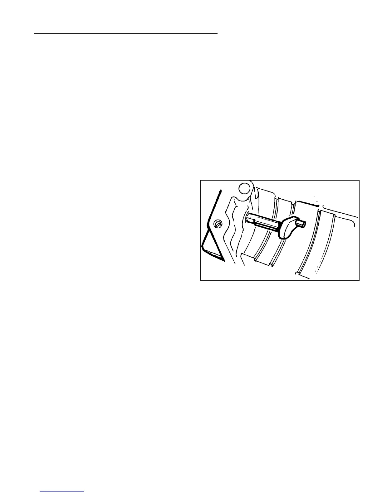
3. Install the displacement control shaft.
4. Install the pump shaft assembly into the housing.
5. Install the bearing spacer washer.
6. Install the lip seal and retaining ring as described in
the minor repair section.
7. Install the cradle bearings.
8. Install the slot guide block onto the displacement con-
trol shaft.
9. Install the swashplate into the housing. The slot on
the swashplate must engage the slot guide block on
the displacement control shaft. Use a tool such as a
screw driver or scribe to hold the guide block in posi-
tion while installing the swashplate.
10. Hold the swashplate in position and measure the end
play of the displacement control shaft using a dial
indicator or a depth gauge. Using a suitable sleeve,
press the control shaft bearing into the housing until
the control shaft end play is between 0.020” and
0.060”.
Figure D-16. Control Arm Installation
 Loading...