5 Electrical Troubleshooting
Ignition Switch / Solenoid Tests
5 - 14
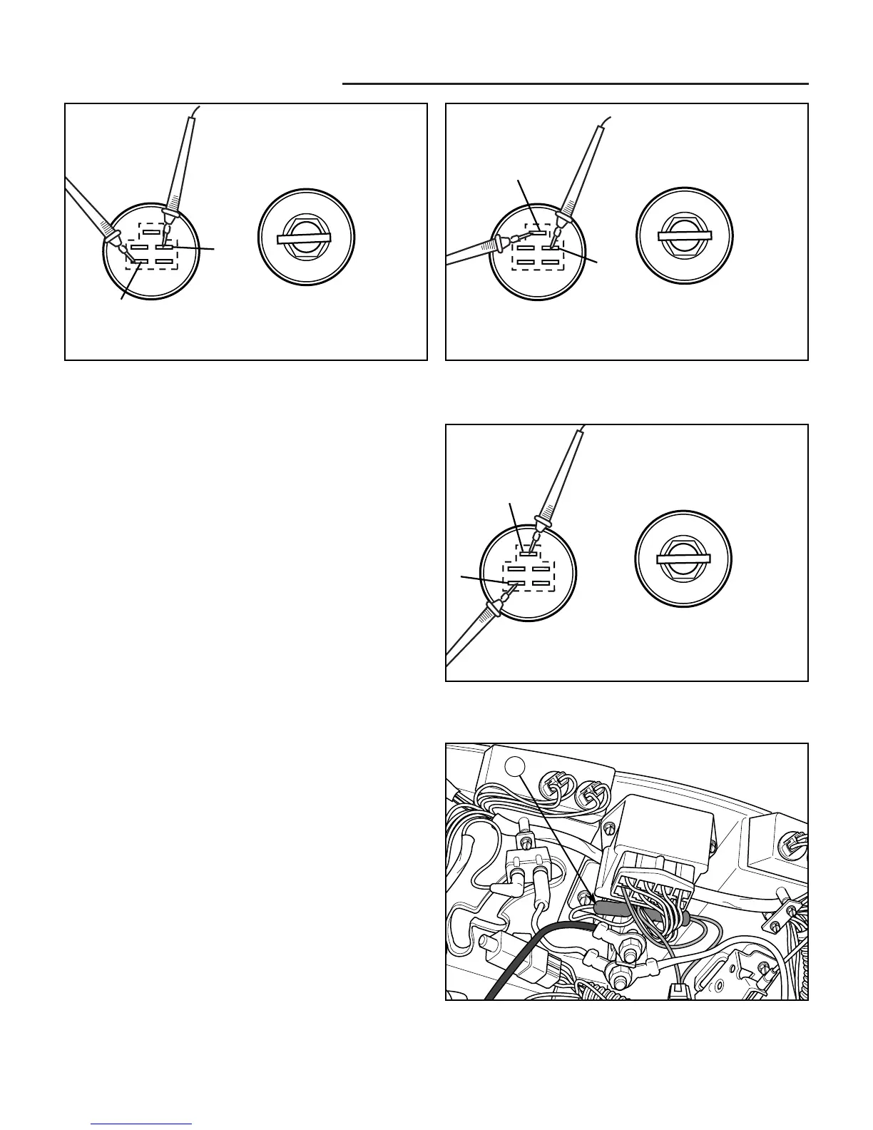
Figure 13. Testing the Ignition Switch
B
S
OFF
RUN
START
Figure 14. Testing the Ignition Switch
L
S
OFF
RUN
START
Figure 15. Testing the Ignition Switch
8. Hold switch in START position. Test the following
connections for continuity: B to L, B to S, L to S.
There should be a reading of 0.3-1.0 ohms (continu-
ity) on the multi-meter (see Figures 13-15).
9. Check all other connection combinations for no conti-
nuity. B to L, B to S, and L to S should be the only
combinations that have continuity; all other connec-
tion combinations should have no continuity.
Replace a switch that does not meet all of the above test
results.
10. Reinstall the ignition switch and reattach the plug.
B
L
OFF
RUN
START
D. Test Power to Solenoid
1. Unplug the blue / white wire (A, Figure 16) from sole-
noid post 1.
2. Probe ground. Probe the blue / white wire plug.
3. Turn the ignition switch to START. The VOM should
show battery voltage. If not, recheck the key switch,
circuit breaker, and all connections.
Figure 16. Solenoid Location
A. Blue/White Wire & Plug
A
 Loading...