6 General Repair
6B Hand Controls Repair
6 -34
7
4
3
8
9
12
11
2
1
5
10
13
6
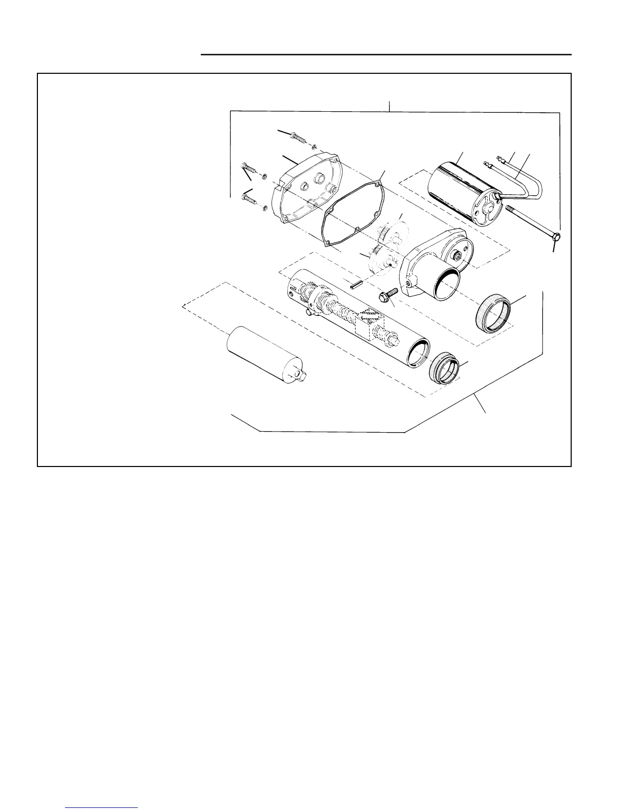
Ref. Desc.
No.
1 Capscrew, Taptite
2 Pin, Drive
3 Motor Kit, 12 VDC
4 Gasket, Housing
5 Seal, Outer Tube (Top)
6 Ball Screw Assm.
7 Motor & Gearbox Assm
8 Brush and Lead (Red)
9 Brush and Lead (Black)
10 Seal, Inner Tube (Top)
11 Output Gear & Slip Clutch Assm.
12 Gear Assm.., 2nd & 3rd
13 Capscrew
14 Screws, Gear Box
15 Gear Box Cover
Figure B-32. Electric Lift Assembly
ELECTRIC LIFT MOTOR, GEAR BOX, AND BALL SCREW
DISASSEMBLY
The electric lift assembly can be replaced as an assem-
bly or in several sub-assemblies. See Figure 32 for a
complete breakdown and assembly groupings.
The following procedure is for complete disassembly. If
complete disassembly is not required, follow the instruc-
tions as far as needed. For reassembly, follow the in-
structions in reverse order.
1. See FIgure 32. Remove the taptite capscrew (1) and
remover the ball screws assembly (6).
2. Remove the gear box cover screws (14), cover (15)
and gasket (4).
3. Remove the gear assembly (12).
4. Remove the drive pin (2) and remove the output gear
and slip clutch assembly (11).
5. Remove the motor kit by removing the two capscrews
(13) from the motor kit (3). Remove the motor kit
from the base.
6. Separate the motor housing from the armature and
remove the brushes and leads.
For reassembly, the brushes can be retained in their
keepers using rubber bands
14
14
15
 Loading...