6 - 51
6 General Repair
6C Foot Controls Repair
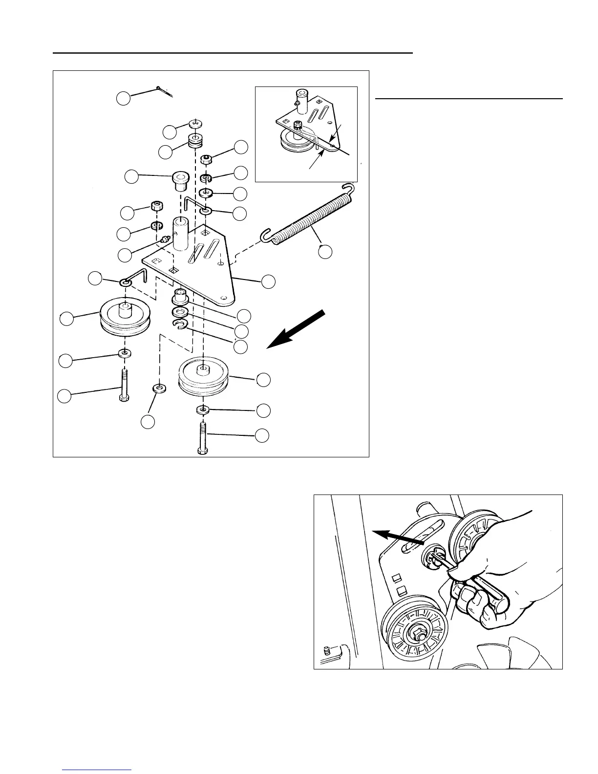
Figure C–22. Idler Arm Assembly - Tuff Torq K215A Models
A. 3/8-16 Hex Nut
B. 3/8" Lockwasher
C. 13/32" Washer
D. Belt Stop
E. Tension Spring
F. Idler Arm Assembly
G. Bushing
H. 5/8" Washer
I. 5/8" Clip Ring
J. "V" Pulley
K. 3/8-16 x 2" Capscrew
L. 11/32" Washer
M. Flat Idler Pulley
N. Grease Fitting
O. Grommet
P. Cotter Pin
.75" - .88"
BELT STOP POSITION
Attach To Rear
Edge - RH Frame
See Inset
Illustration
FRONT
Idler Arm Assembly Service -
Tuff Torq K215A Models
1. Remove the mower deck to provide access to idler
arm assembly components.
2. Remove the tension spring (E. Figure C–22).
2. Remove the brake rod as described in Brake Rod
Service.
3. Remove the clutch rod as described in Clutch Rod
Service.
5. Loosen the idler pulley (M) and remove the drive belt
from the idler arm assembly.
4. Remove the clip ring (I and remove the idler arm
assembly.
Inspect and repair as necessary. Reinstall in reverse
order of disassembly.
Figure C–23. Remove Clip ring
L
O
G
A
B
N
D
M
C
K
L
K
C
J
F
E
D
C
B
A
P
REF.
LTR. DESCRIPTION
I
H
G
 Loading...