7 - 22
7 Transmission Repair
7B Sauer-Sundstrand BDU-21L-207
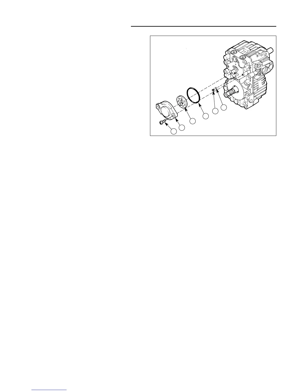
REASSEMBLY
1. Prior to installing the charge pump, apply a small
quantity of petroleum jelly to the l.D., O.D., and side
faces of the gerotor assembly.
2. Install the charge relief valve ball and spring.
3. Install the charge pump drive pin.
4. Install the charge pump gerotor assembly.
The charge pump rotation is determined by the orienta-
tion of the charge pump cover on the center section or
end cap. The cast flat on the cover indicates the orienta-
tion (see figure B-12).
5. Install the charge pump cover and O-ring. The charge
relief valve spring must enter the recess in the cover.
6. Install the charge pump cover screws. Torque the 5
mm screws to 84 to 120 in.lbs. (9.8 to 13.6 Nm).
Torque the 6 mm screws to 138 to 180 in.lbs. (16 to
20 Nm).
A
B
C
D
F
E
Figure B-14. Charge Pump Assembly
A. Capscrew B. Charge Pump Cover
C. Gerotor Assembly D. O-Ring
E. Charge Relief Spring E. Charge Relief Ball
 Loading...