6-29
6 General Repair
6B Hand Controls Repair
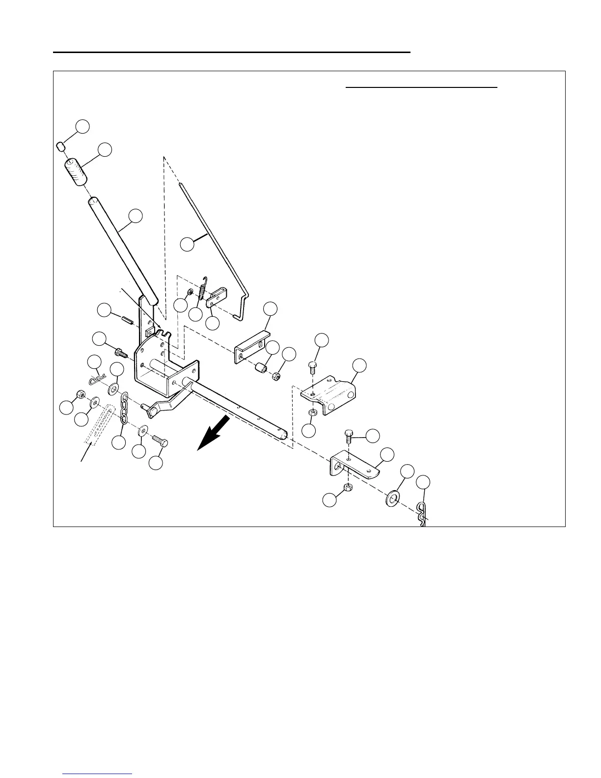
LIFT LEVER ASSEMBLY
Models With Single Lift Arm
G
D
F
C
B
A
E
T
V
U
O
H
I
K
L
K
M
N
J
O
J
J
S
Q
R
Q
P
Mower Arm
A. Thumb Button
B. Lift Lever Grip
C. Lift Lever Assm.
D. Latch Rod
E. Push-on Nut
F. Spring
G. Lift Lever Latch
H. Lift Guide Bracket
I. Spacer
J. Hex Locknut 5/16-18
K. Hex Head Capscrew 5/16-18 x 7/8"
L. Lift Mounting Bracket Assembly
M. Lift Pivot Bracket
N. Flat Washer
O. Hitch Pin Clip
P. Hex Head Capscrew 5/16-18 x 1-1/2"*
Q. Flat Washer*
R. 4-Link Lift Chain*
S. Hex Lock Nut 5/16-18
T. Flat Washer*
U. Hex Head Capscrew 5/16-18 x 1-1/4"
V. Roll Pin
LIFT LEVER ASSEMBLY PARTS
(Early style
has only 1
notch )
*Early models only
FRONT
OF UNIT
Figure B–26. Single Arm Lift Lever Assembly
SINGLE CHAIN - MANUAL LIFT LEVER REMOVAL
The entire lift lever assembly may be easily removed
from the unit for bench inspection and repair:
1. Remove the mower deck as described in Mower
Deck Repair.
2. Remove two 5/16-18 x 1-1/4" capscrews, locknuts
and spacers (U, I, & J, Figure B–26) that secure the
lift lever assembly to right side of the unit's frame.
Slide the lift guide bracket (H, Figures B–26) up and
out of position between the frame and the lift lever
mounting bracket.
3. Remove the hitch pin clip (O, Figure B–26 ), and flat
washer (N, Figure B–26) from lift lever arm shaft at
left side of unit.
4. Slide the lift lever assembly straight out of lift pivot
bracket (M, Figures B–26) and out of engagement
with pins in underside of lift mounting bracket assem-
bly (L, Figures B–26).
5. The lift lever assembly may now be moved to a work-
bench for additional inspection and any required ser-
vicing.
7. Visually inspect all parts for wear, corrosion, or dam-
age, and replace as necessary.
Single Chain Manual Lift
 Loading...