ELECTRICAL SYSTEM 6-17
IGNITION SYSTEM
DESCRIPTION
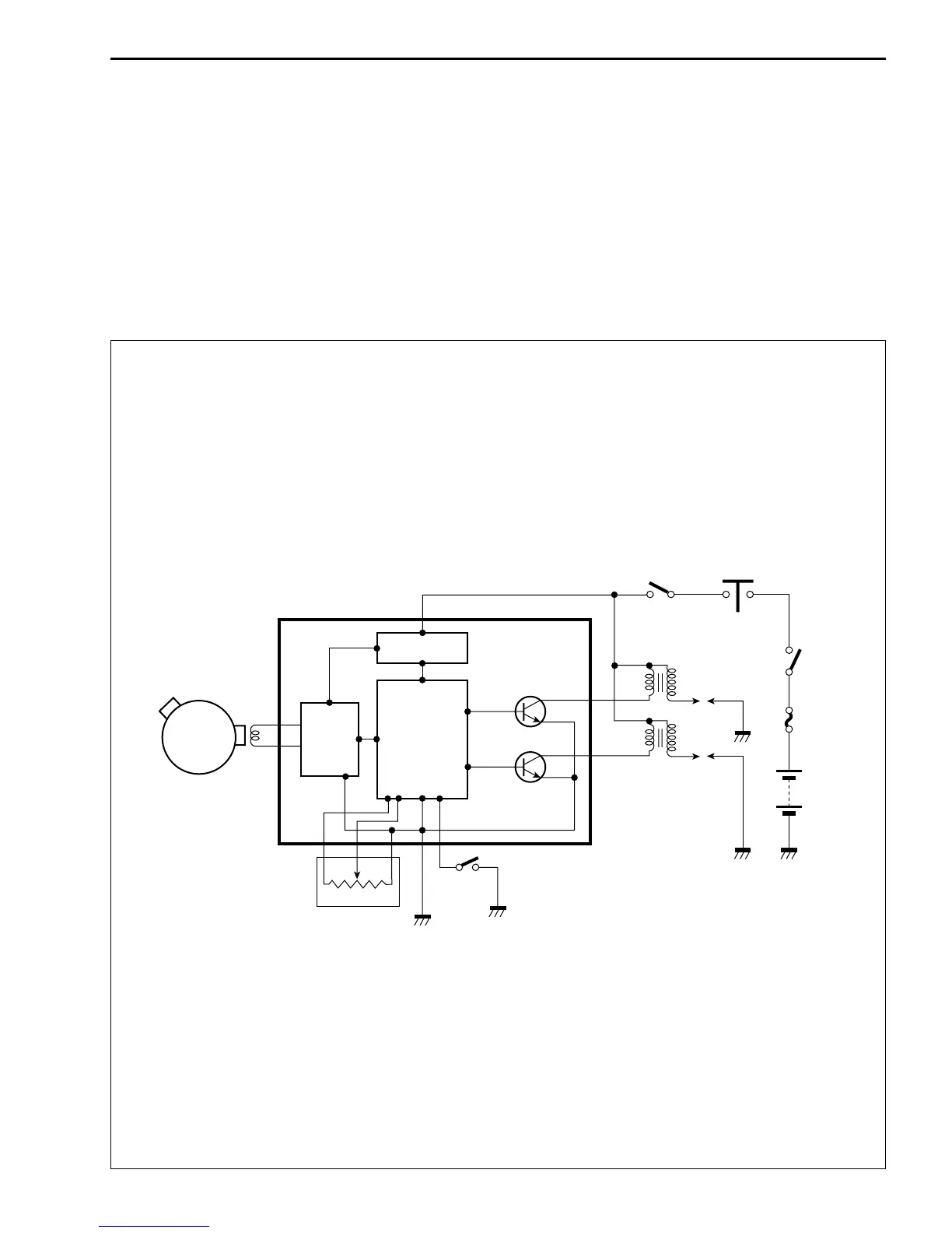
The fully transistorized ignition system consists of the following components: a generator, ignitor, throttle
position sensor, neutral switch, ignition coil and spark plug. The ignition timing is programmed and stored in
the ignitor.
The pick-up coil is mounted in the generator. The induced signal in the pick-up coil is sent to the wave-form
arrangement circuit and the CPU receives this signal and calculates the best ignition timing, throttle position
sensed by throttle position sensor and data stored in the ROM. The CPU outputs the signal to the transistor
of the ignition coil output circuit which is connected to the primary windings of the ignition coil which is turned
“off” and “on” accordingly. Thus, it induces the secondary current in the ignition coil’s secondary winding and
produces the spark between the spark plug gap.
Signal generator
Wave
form
arrange-
ment
circuit
CPU
(Central
Processing
Unit)
Power
source circuit
Ignitor
TPS
Gear
position
switch
Ignition
coil R
Ignition coil F
Engine stop
switch
Side-stand
relay
Ignition
swich
Battery

 Loading...