TB7300 Installation and Operation Manual Description 21
© Tait International Limited December 2022
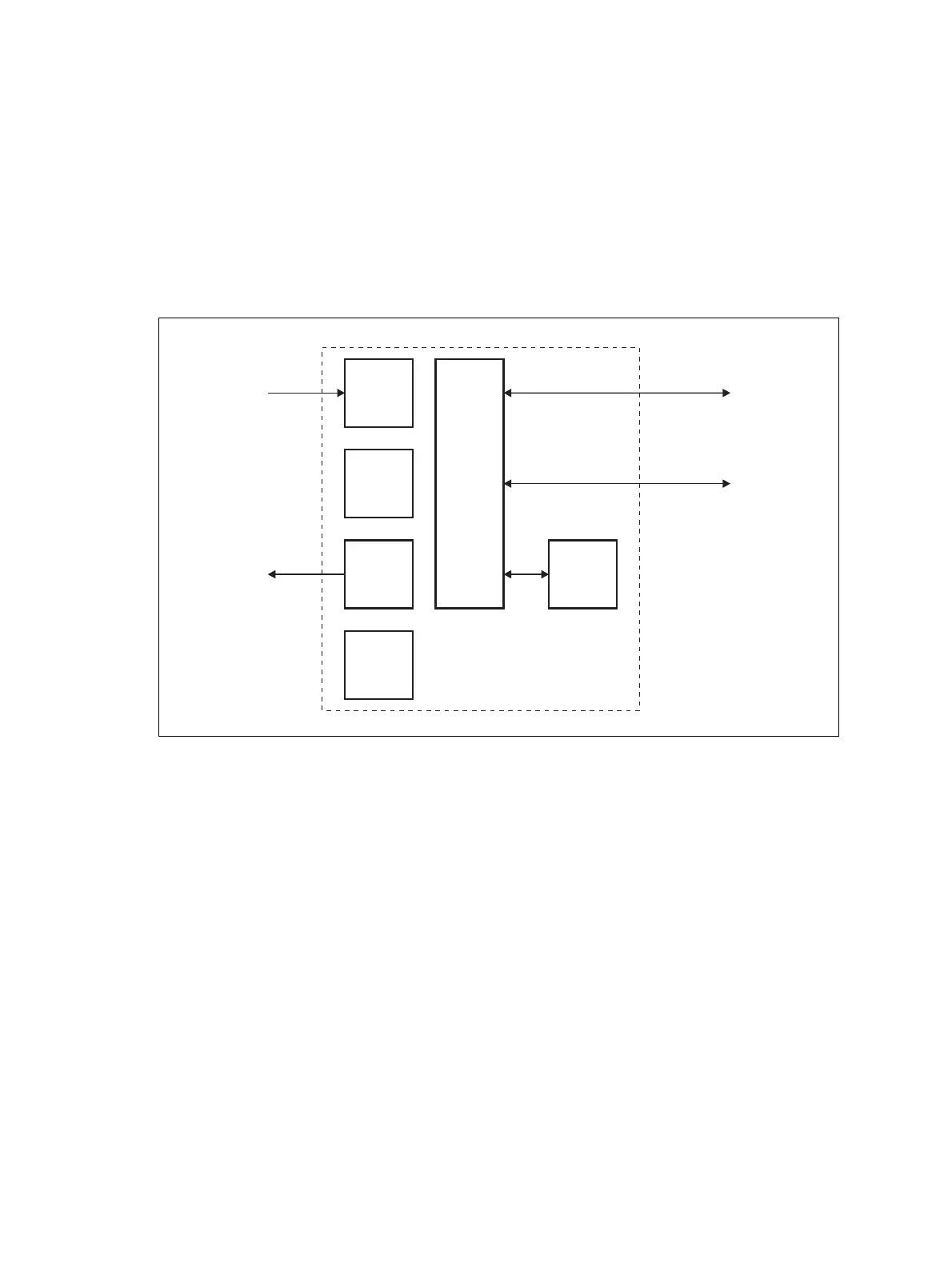
1.6 Theory of Operation
The RF input is fed directly to the receiver board, while the RF output is
via the exciter and PA boards. The control board also receives signals from,
and sends signals to, the system interface, the Ethernet interface, and the
front interface (see Figure 1.1).
The Ethernet interface carries VoIP and also allows maintainer access via
a web browser.
The control board carries out signal processing and has overall control of
the base station.
The control board converts information between analog and digital and
controls the maintainer’s access via the Ethernet interface. It performs the
air interface signal processing for digital DMR and P25 operation, gives the
base station an identity as a network element, and provides the physical
connections for the Ethernet and system interfaces.
Figure 1.1 Base station high-level diagram
RF Input
RF Output
Receiver
Board
PA
Board
Supply
Interface
Board
Exciter
Board
Front
Interface
Control
Board
System Input
and Output
Ethernet Interface
to Network