TB7300 Installation and Operation Manual Appendix C Testing with the TBA0STU Calibration Test Unit 87
© Tait International Limited December 2022
Connecting the CTU to the RJ45 from a TBC101A E&M Isolation Adaptor
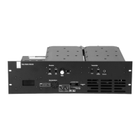
Connect the power input of the CTU to the PMU auxiliary output.
Connect the RJ45 patch cable to the E&M isolation adaptor and the RJ45
connector on the CTU
1).
The CTU is compatible with the TB9100 and TN9110 network gateway
configuration on page 14 of the Base Station E&M Isolation Adapter
document (TD-0052-xx).
The CTU needs to be powered externally from a 12V to 32V supply for the
E&M key switch
1( to work.
The RX gate output and LED
2! will light when the RX gate is open.
Available Tests
Checking the Balanced Line Input and Output Levels
For analog mode only.
On the WebUI, go to Diagnose > Analog Line.
The headings refer to the sections on the WebUI page.
Checking Audio Input
1. Put the base station online.
2. Connect an audio generator set to -10dBm @ 1kHz (this is the
factory default line level) to the Line Input BNC connector of the
CTU.
3. The audio input measured by the reciter is displayed as the
“Measured RMS level” at the top right of the page. The configured
level is also displayed.
4. The configured line input level is the audio level for 60% system
deviation and can be set in the Configure > Analog line Audio input
section on the WebUI. Connecting a service monitor to the PA and
switching the TX Key switch to On should measure 60% system
deviation at the configured audio level.
