To use.
■
Click the Trigger Type box and select Bus from the drop-down list.
■
Click the Bus box and select the bus number or name from the drop-down list.
NOTE. You have the option to add a user-defined label for bus sources.
■
Click the Logic Thresholds Setup button to set the voltage threshold levels for the channels in the bus.
■
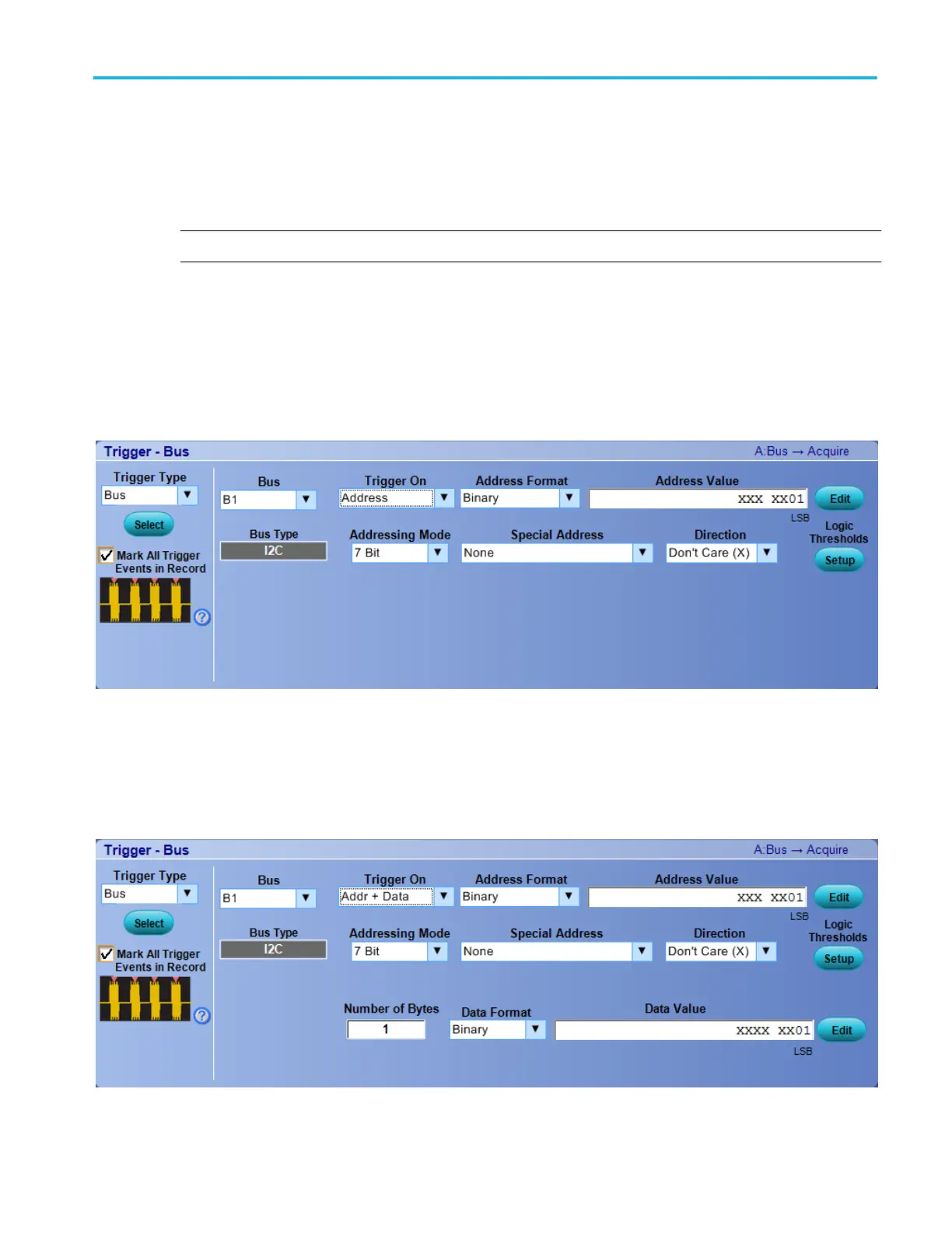
Select the type of bus cycle or activity to use as the trigger from the Trigger On drop-down list.
■
For some Trigger On selections, you need to set additional fields to define other parameters such as for an Address.
In the following example, you need to set an Address Format, Address Value (click the Edit button), Data Direction, and
Addressing Mode. Optionally, you can also set the component threshold levels through the Logic Thresholds Setup button.
In the following example on MSO/DPO5000B Series instruments, you need to set an Address Format, Address Value (click
the Edit button), Addressing Mode, Special Address, Direction, Number of Bytes, Data Format, Data Value (Edit) for the
Addr+Data Trigger On type. Optionally, you can also set the component threshold levels through the Logic Thresholds
Setup button.
Trigger setups
DPO70000SX, MSO/DPO70000DX, MSO/DPO70000C, DPO7000C, and MSO/DPO5000B Series 387
 Loading...

