When using Envelope with Edge trigger on a signal as shown, positive polarity triggers on the leading edge of the burst, while
negative polarity triggers on the trailing edge of the burst. Polarity changes have similar effects on the other trigger types where
the Envelop Detector is available.
Set the trigger reset conditions
1. In Trigger Reset Type drop-down menu, select a condition for a trigger reset.
2. Use the drop-down menus to set up Time, Transition, State, Source, or Threshold conditions for the specified reset.
Trigger settings (Shared - independent)
This feature determines how the instrument applies trigger levels to the input channels:
■
Shared. Sets the trigger level in common across all input channels. Changing the trigger level of one channel changes the
trigger levels of all input channels to the same level.
■
Independent. Allows you to set a unique trigger level for each input channel. Changing the trigger level on one channel
does not affect the trigger level setting of the other input channels.
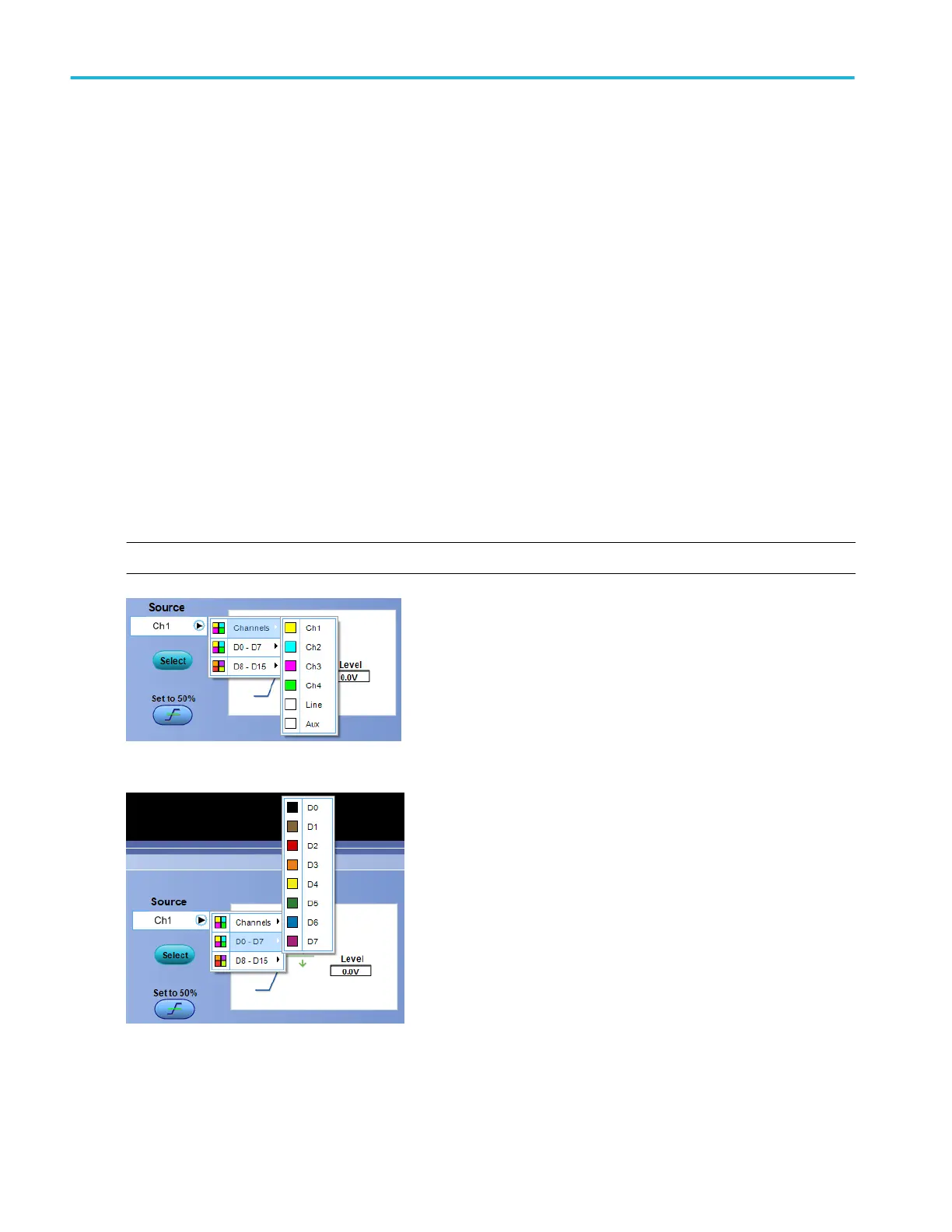
Trigger source
The trigger source determines the source of the trigger signal. The input channels are the most commonly used trigger sources
and are available for all trigger types.
NOTE. You have the option to add user-defined label for analog, reference, bus, and digital sources.
Figure 31: To trigger on an input channel, select a channel.
Figure 32: If your instrument has digital channels, trigger on a digital channel by selecting a digital channel.
Oscilloscope reference
838 DPO70000SX, MSO/DPO70000DX, MSO/DPO70000C, DPO7000C, and MSO/DPO5000B Series
 Loading...

