Then the typical sequence is to connect the DUT between the oscilloscope and the signal generator or AWG for actual testing.
After recabling, only a reSync and Run are needed, even for Bit testing, because the signal test pattern has already been
acquired into the oscilloscope memory.
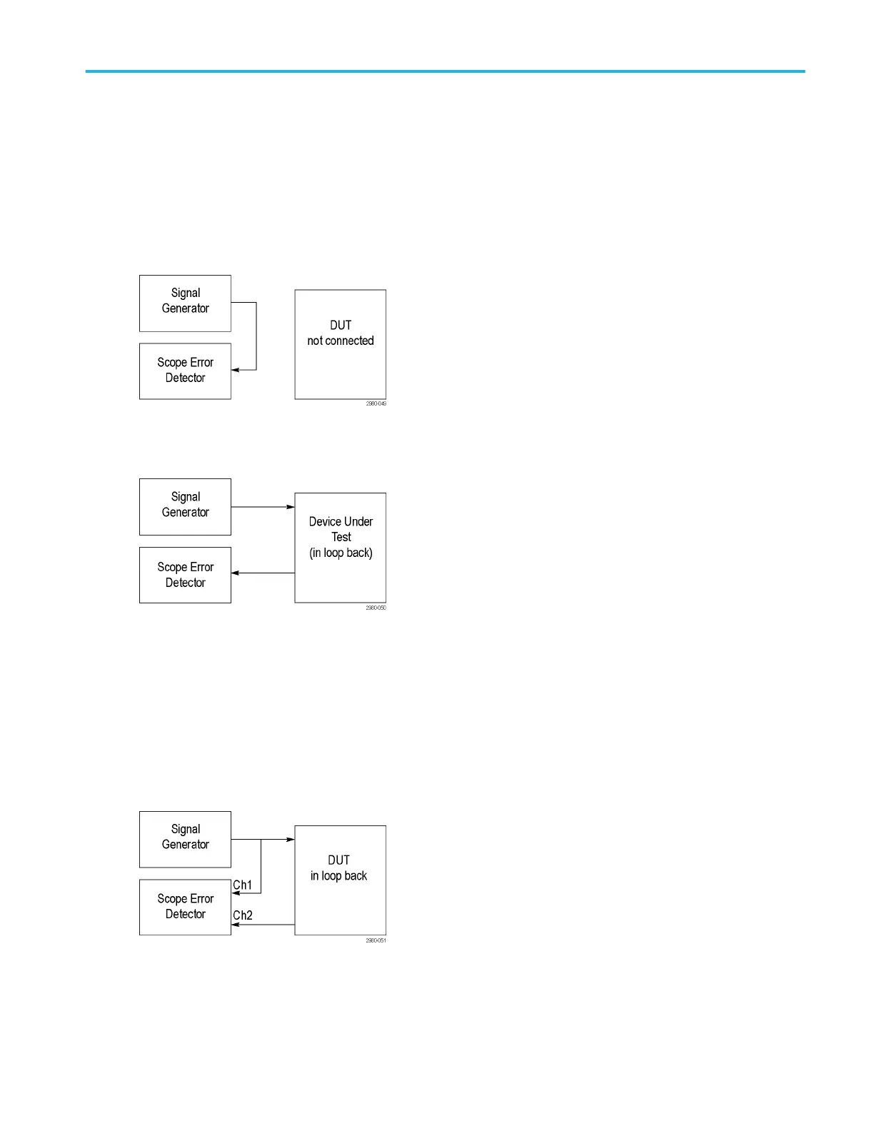
There are several cable arrangements you can use with the Serial Error Detector. The first cable setup specifically applies to
SATA, PCIe, and generic 8b10b bit testing, when a Learn operation is required to acquire the signal test pattern into Error
Detector memory. However, you can use this same cable arrangement to verify Error Detector operation.
Connect the cabling as shown for the Learn operation in SATA, PCIe, and generic bit testing.
Having done the Learn operation, you can now insert the DUT in-between the Signal Generator and the Error Detector as shown.
With the DUT inserted between the Signal Generator and the Serial Error Detector, all you need to do to get the Error Detector
running is to press the Sync and Run buttons, because the Learn operation was completed in the previous step. If you do
another Learn operation, you risk learning errors created by the DUT.
To avoid having to rearrange the cables after the Learn operation, you may split the output of the signal generator, putting one
branch into the Error Detector and one branch into the DUT. Here the Learn Operation is done on Ch1, but the actual error
detection occurs on Ch2. You can adjust the amplitude of the signal generator to account for the loss due to splitting the signal.
This works because the Error Detector learn operation stores the signal test pattern into error detector memory, not channel
memory.
When the Error Detector is driven from the user interface, bus triggers are used whenever possible, so that bus decoding is
automatically enabled. The Decoding indicates the location of the error in the signal by highlighting the decoded value in red, as
shown in the screen capture below. You can use additional oscilloscope channels to simultaneously probe other signals to debug
the cause of the error.
Error detector setups
DPO70000SX, MSO/DPO70000DX, MSO/DPO70000C, DPO7000C, and MSO/DPO5000B Series 209
 Loading...


