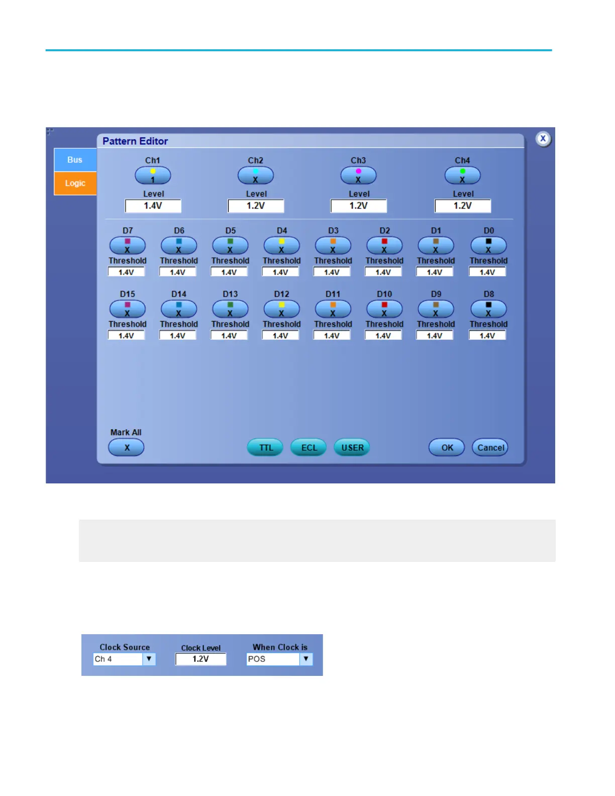
Logic pattern and state pattern editor (digital tab)
Use the controls to set up the Logic Pattern or the Logic State trigger pattern of the channels the instrument uses as logic
waveforms to detect a bus value.
What do you want to do next?
Learn how to define a pattern for the instrument to use to detect a bus value.
Learn about bus setups.
Logic clock inputs
For the supported instruments, you need to connect one of the channel inputs to a clock signal. The instrument combines all of
the channel inputs to form a logic pattern.
Oscilloscope reference
780 DPO70000SX, MSO/DPO70000DX, MSO/DPO70000C, DPO7000C, and MSO/DPO5000B Series

 Loading...


