Aliasing
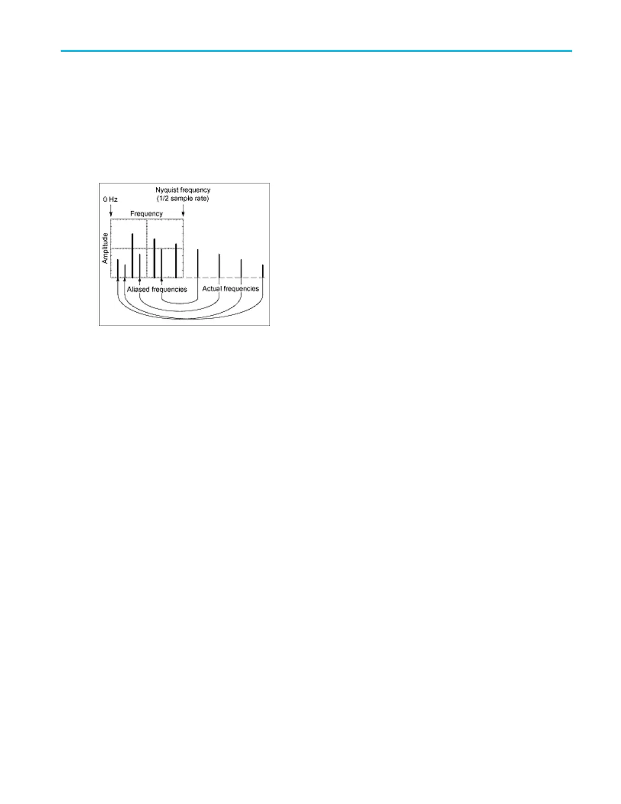
Problems occur when the instrument acquires a signal containing frequency components that are higher in frequency than the
Nyquist frequency. The frequency components that are above the Nyquist frequency are under sampled and appear to "fold
back" around the Nyquist frequency, showing as lower frequency components. These incorrect components are called aliases.
To quickly check for aliasing, slowly decrease the horizontal time scale. If the shape of the displayed waveform changes
drastically or becomes stable, your waveform is probably aliased. You can also check for aliasing by turning on peak detect
acquisition mode. To remove aliasing, modify the record length.
■
Continue
■
Previous
Eliminate aliasing
Use the following methods to eliminate aliases:
■
Increase the sample rate by adjusting the horizontal scale to a faster time-per-division setting. Since you increase the
Nyquist frequency as you increase the time per division, the aliased frequency components should appear at their proper
frequency. If the increased number of frequency components shown on the screen makes it difficult to measure individual
components, use MultiView Zoom to magnify the FFT waveform.
■
Use a filter on the source signal to limit the bandwidth of the signal to frequencies below that of the Nyquist frequency. If the
frequency components that you want to view are below the built-in bandwidth settings, set the source channel bandwidth to
the appropriate value.
■
Push the Autoset button.
■
Switch the acquisition to Envelope mode or Peak Detect mode. Envelope mode searches for samples with the highest and
lowest values over multiple acquisitions and can detect faster signal components over time. In Peak Detect mode, the
acquisition alternates between saving the highest sample in one acquisition interval and lowest sample in the next
acquisition interval.
■
Beginning of Overview
■
Previous
Math setups
DPO70000SX, MSO/DPO70000DX, MSO/DPO70000C, DPO7000C, and MSO/DPO5000B Series 259