Window attributes.
■
In the time domain, windows are typically bell shaped and go to zero at the ends of the record. For cases where you may be
doing impulse response testing, the impulse should be centered at the zero phase reference point (for most windows, this is
the 50% position of the gate and 20% for the Tek Exponential window).
■
Different window functions affect the resolution bandwidth of the spectral analyzer.
■
Various window shapes affect the scallop loss.
■
The shape of the frequency domain lobe is determined by the window function. Some windows have better resolution
bandwidth, but they do so at the expense of side lobe attenuation and energy leakage into adjacent bins. For example, a
rectangular window typically spills energy into many bins showing signals that don’t exist; but it has the best frequency
resolution. If you are using a window where leakage is occurring, you may want to use spectral gating to reduce the
amplitude errors when measuring a given frequency.
Scallop loss
Scallop loss is the difference between the actual magnitude and the computed magnitude of a signal that is halfway between two
frequency bins in the spectral output data. Scallop loss is only noticeable when the spectral analyzer is not using zero-fill such as
when it is set to full span.
If zero-fill is in use, frequency domain interpolation occurs and there is minimal scallop loss. Zero-fill cannot be directly controlled;
it is affected by changing settings of resolution bandwidth or gate width. When in use, a minimum of 20% of the FFT input is
always zero, effectively removing scallop loss error by interpolating in the frequency domain.
NOTE. For most settings, descriptions of amplitude accuracy due to scallop loss (as discussed in other publications) do not apply
to this oscilloscope when used as a spectral analyzer because of zero-fill. Full span is the most likely setting where scallop loss
might occur.
Leakage
Leakage results when the time domain waveform used to create the FFT function is periodic but contains a noninteger number of
waveform cycles. When the record contains a fraction of a cycle, there are discontinuities at the ends of the record.
These discontinuities cause energy from each discrete frequency to leak over on to adjacent frequencies. This results in
amplitude errors when measuring any given frequency. Different windows have different leakage characteristics.
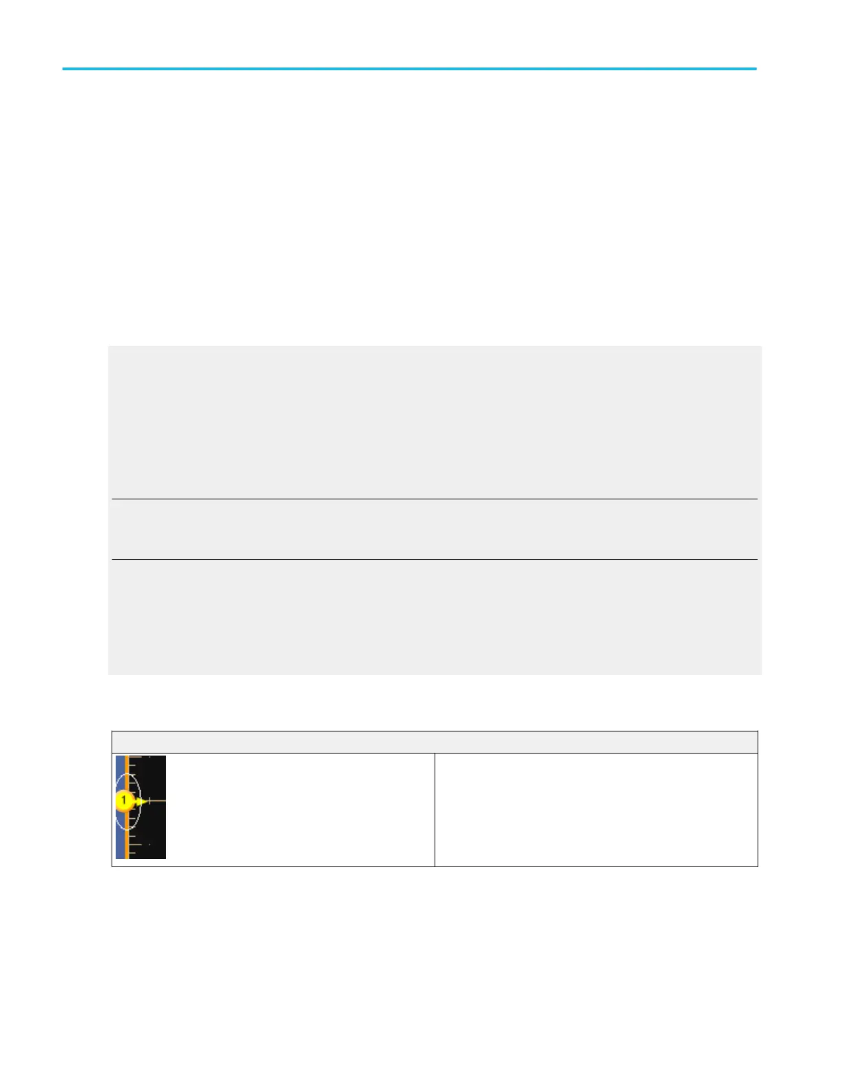
Selected waveform versus deselected waveform
Waveform handle
The waveform handle indicates if a waveform is selected or
deselected.
The waveform handle is outlined in the same color as the
graticule when the waveform is selected. The waveform handle
is outlined in black when a waveform is deselected.
Oscilloscope reference
822 DPO70000SX, MSO/DPO70000DX, MSO/DPO70000C, DPO7000C, and MSO/DPO5000B Series
 Loading...


