EasyManua.ls Logo

Tektronix MDO34 User Manual

Tektronix MDO34
282 pages
To Next Page IconTo Next Page
To Previous Page IconTo Previous Page
Page #115 background image
See also
Measurement Name panel (Measurement configuration menu) on page
111
Global Measurement Settings panel (Measurement configuration menu) on page 112
SOA Mask definition controls and fields
Use the SOA Mask dialog to configure the parameters to add point, delete point, save mask, and recall mask.
Use the parameters to define the linear mask for an SOA measurement.
Define Mask fields and controls
Field or control Description
Define Mask
Select between defining a mask by setting limits or defining points. Use Set Points to define
a more complex mask with up to 10 points, each of which you can define.
Maximum Voltage Define the safe operating area by creating a four-point mask by setting the maximum
voltage, current, and power
.
Maximum Current
Maximum Power
Define Mask Define the voltage (X) and amperage (Y) for each mask point.
X (Volts)
Define voltage values for the mask point.
Y (Amps)
Define current values for the mask point.
Insert Point
Add voltage and current points to define mask. Points are added to the end of the existing
list.
Delete Point
Deletes the selected point data row.
Clear Table Clears the values of the mask coordinates in the table.
Reference Levels panel (Power measurement configuration Menu)
Use the Global Measurement Settings panel to set the reference levels, the units used to take measurements, gating, and the method
used to calculate the High and Low waveform values.
See Global Measurement Settings panel (Measurement configuration menu) on page 1
12 for the Reference panel fields and controls.
Other measurement settings panels
Power Measurement Name panel (Measurement configuration menu) on page 114
Bus configuration menu
Use the Bus menu to select the bus type to display, configure the input sources, and set how to display the bus on the screen.
To open the Bus configuration menu:
For an existing bus, double-tap the Bus badge in the Settings bar.
Menus and dialog boxes
3 Series Mixed Domain Oscilloscope Printable Help 115

Table of Contents

Other manuals for Tektronix MDO34

Question and Answer IconNeed help?

Do you have a question about the Tektronix MDO34 and is the answer not in the manual?
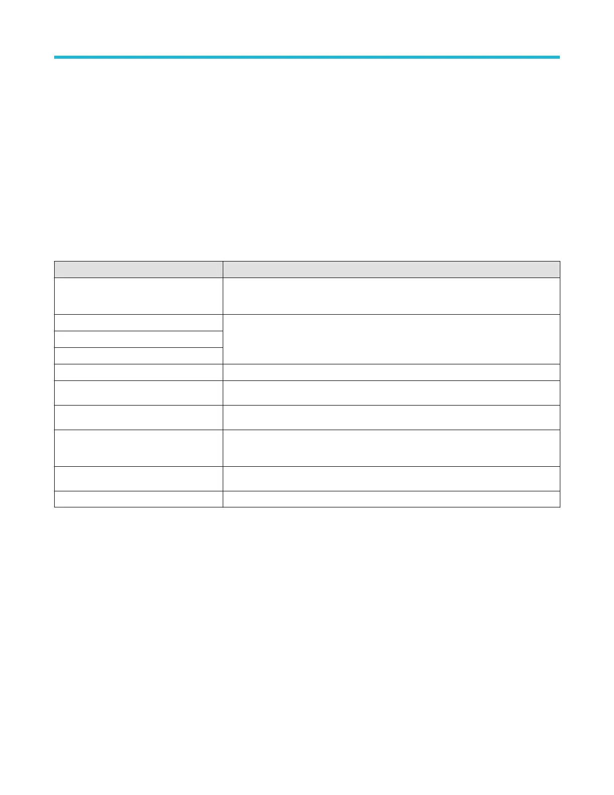
Tektronix MDO34 Specifications

General IconGeneral
Analog Channels4
Sample Rate2.5 GS/s
Record Length10 Mpoints
Mixed Domain AnalysisYes
Waveform Capture Rate>280, 000 wfms/s
Spectrum Analyzer Frequency Range9 kHz to 3 GHz
Vertical Resolution8 bits
Input CouplingAC, DC, GND
Operating Temperature0°C to +50°C
Digital Channels16
ConnectivityUSB, LAN, HDMI
Arbitrary Function Generator50 MHz
Trigger TypesEdge, Pulse Width, Runt, Logic, Setup/Hold, Rise/Fall Time, Video
Input Impedance1 MΩ
Maximum Input Voltage300 Vrms
Dimensions140 mm
Weight4.5 kg
Bandwidth100 MHz, 200 MHz, 350 MHz, 500 MHz
Display10.1-inch capacitive touch HD display
Voltmeter4-digit

Summary

Welcome to the 3 Series MDO instrument help

MDO34, MDO32 Key features and benefits

Lists the primary capabilities and advantages of the MDO34 and MDO32 models.

Accessories

Standard accessories

Lists items included by default with the instrument for basic operation.

Recommended probes

Details various probes compatible with the oscilloscope for different measurement needs.

Factory options

Bandwidth options

Lists available bandwidth upgrades for analog channels and spectrum analyzer.

Serial bus decode and trigger options

Lists options for decoding and triggering various industry-standard serial buses.

Power Analysis option

Describes the option for advanced power measurements like quality, loss, and harmonics.

Option upgrades

How to install an option license

Provides a step-by-step guide for installing software license keys to enable instrument features.

Install your instrument

Check shipped accessories

Verifies that all standard accessories and ordered items have been received with the instrument.

ESD prevention guidelines

Provides techniques to avoid electrostatic discharge damage to the instrument and probes.

Getting acquainted with your instrument

Front panel controls and connectors

Identifies front panel controls and connectors for direct access to instrument settings and inputs.

Trigger controls

Describes controls for setting trigger level, slope, and mode for capturing events.

Horizontal controls

Details controls for setting horizontal scale, position, and record length for waveform display.

Identifying items in the time domain display

Identifies key user interface elements within the time domain display for better understanding.

Configure the instrument

Download and install the latest firmware

Explains how to download and install the latest instrument firmware for improvements.

Run Signal Path Compensation (SPC)

Guides on running SPC for accurate measurements and compensating internal signal path variations.

Compensate TPP0250, TPP0500B, or TPP1000 probes

Details how to adjust probe high-frequency response for accurate measurements and automatic compensation.

Analog channel operating basics

Acquiring a signal

Explains setting scale and position parameters for analog signal acquisition.

Quickly display a waveform (autoset)

Guides on using the Autoset function to automatically display a triggered waveform.

Add a measurement

Guides on selecting and adding measurements to display in the Results bar.

Acquiring digital signals

Connect and set up digital signals

Guides on setting up digital channels using the Digital Channel configuration menu to acquire signals.

Add a serial bus to the Waveform view

Explains how to add serial bus waveforms for decoding and display using Bus configuration.

Advanced triggering

Triggering concepts

Explains the fundamental concepts of user-defined trigger conditions for capturing waveforms.

Set Trigger Holdoff

Explains setting holdoff time to stabilize triggering on undesired events or burst signals.

Customizing measurements

Set measurement reference levels

Guides on setting reference levels (high, mid, low) for accurate time-related measurements.

Set measurement gates

Explains specifying waveform portions for measurements using gating (off, screen, cursors).

Saving and recalling information

Save a waveform to a file

Explains saving channel waveform data to CSV or WFM files for analysis.

Recall a Setup file

Guides on loading and configuring instrument settings from a saved setup file.

The Acquisition configuration menu

Add Measurements configuration menu overview

Time Measurements panel

Trigger configuration menu overview

Trigger types

Describes available trigger types: Edge, Pulse Width, Timeout, Runt, Logic, Setup & Hold, Rise/Fall, Video, Bus, Sequence.

Measurement concepts

Taking automatic measurements in the time domain

Guides on taking automatic measurements like amplitude, period, and frequency.

Taking manual measurements with cursors

Explains using on-screen cursors for manual measurements on acquired waveform data.

Making automated power measurements

Guides on acquiring, measuring, and analyzing power signals with the 3-PWR option.

Math waveforms

Using FFT

References

Upgrading firmware

Provides steps to upgrade instrument firmware using a USB flash drive.

Related product manuals