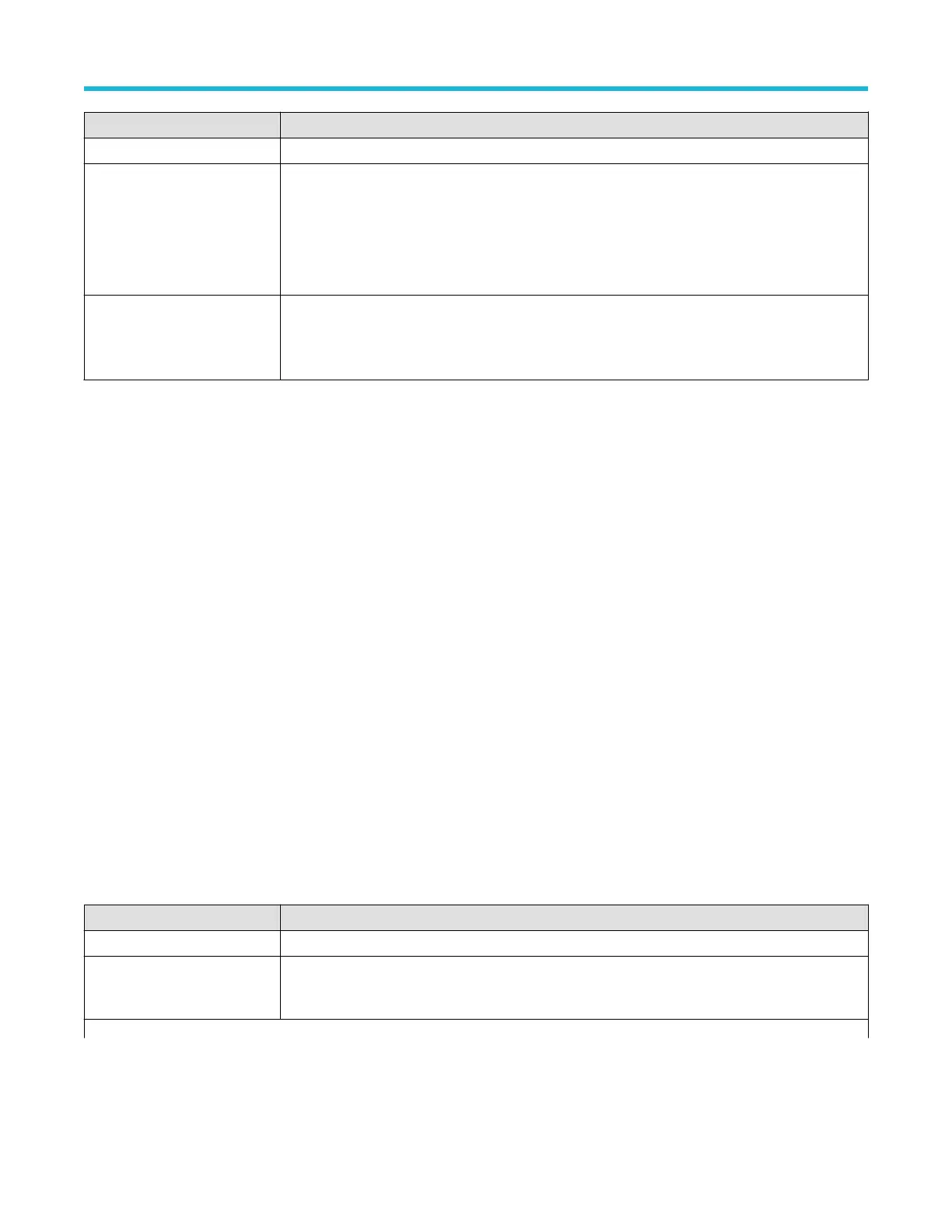
Field or control Description
Slope Sets the signal transition direction to detect. (rising, falling, or either direction).
Mode & Holdoff
Trigger Mode determines how the instrument behaves in the absence or presence of a trigger event.
Holdof
f sets the amount of time the oscilloscope waits after a trigger event before detecting and
triggering on the next trigger event.
For additional information on Trigger Mode, Holdoff, forcing a trigger, and the Trigger Frequency
Counter see Mode and Holdoff panel on page 226.
Act On Trigger
Set the actions the instrument takes when a trigger event occurs.
For additional information on the Act On Trigger panel see Act On Trigger configuration
menu on page 227.
Trigger types
Use the following links to see more information on specific trigger types.
• Edge T
rigger menu
• Pulse Width Trigger menu
• Timeout Trigger menu
• Runt Trigger menu
• Logic Trigger menu
• Setup & Hold Trigger menu
• Rise/Fall Time Trigger menu
• Video Trigger menu
• Bus Trigger menu
• Sequence Trigger menu
Logic Trigger configuration menu
Use the Logic trigger to trigger the oscilloscope when the specified logic conditions occur on any combination of analog and digital inputs.
The logic conditions include the state of each input, the condition to test (inputs go true, false, or are within a time limit), and the Boolean
function of the inputs.
To open the Logic Trigger menu:
1. Double-tap the Trigger badge on the Settings bar.
2. Set the Trigger Type to Logic.
Settings panel (Logic Trigger configuration menu) - fields and controls
Field or control Description
Use Clock Edge? Enables or disables finding logic patterns that occur on the specified clock edge.
Logic Pattern Define Inputs Opens the Logic T
rigger - Define Inputs menu where you define the logic state (High, Low, or Don't
Care), and the signal threshold level that defines the logic state (high or low), for each analog or digital
signal. See Logic Trigger - Define Inputs configuration menu on page 218.
Table continued…
Menus and dialog boxes
3 Series Mixed Domain Oscilloscope Printable Help 216

 Loading...


