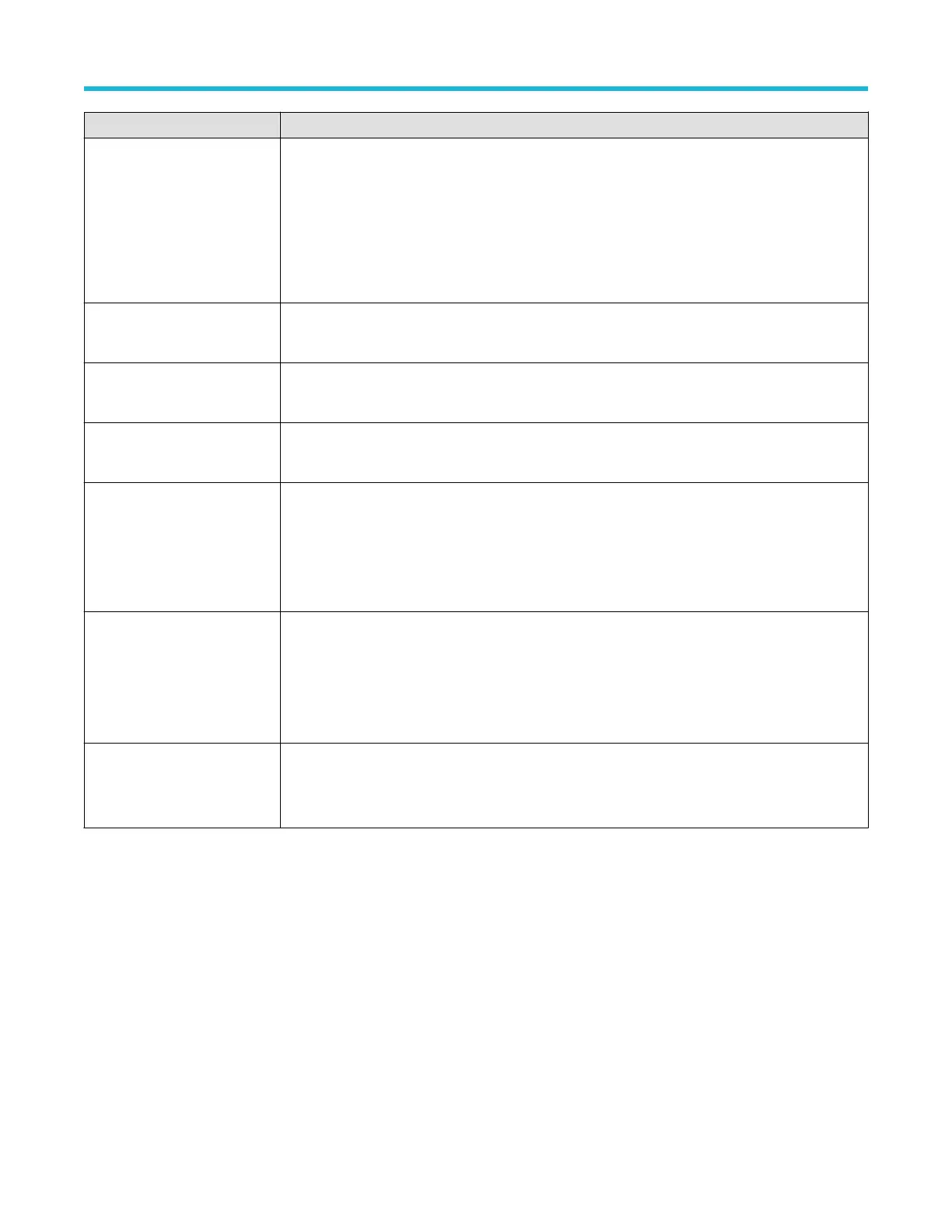
Field or control Description
Trigger When
(Use Clock Edge = No)
Defines the waveform condition on which to trigger.
• Goes T
rue: All conditions change to a true state.
• Goes False: All conditions change to a false state.
• Is True > Limit: Condition remains true longer than a specified time.
• Is True < Limit: Condition remains true for less than a specified time.
• Is True = Limit: Condition remains true for a specified time (within ± 5%).
• Is True ≠ Limit: Condition does not remain true for a specified time (within ± 5%).
Clock Source
(Use Clock Edge = Yes)
Sets the signal to use as the clock. The clock signal can be a digital or analog waveform
Clock Edge
(Use Clock Edge = Yes)
Sets the signal transition edge (rising, falling, or either) for evaluating the logic condition at the clock
transition.
Clock Threshold
(Use Clock Edge = Yes)
Sets the threshold level that the clock signal must pass through to be considered a valid transition. The
clock threshold value is independent of the input signal threshold(s).
Define Logic
Sets the logic condition that must occur with all inputs.
• AND: All conditions are true.
• OR: Any condition is true.
• NAND: One or more conditions are true.
• NOR: No conditions are true.
Mode & Holdoff
Trigger Mode determines how the instrument behaves in the absence or presence of a trigger event.
Holdoff sets the amount of time the oscilloscope waits after a trigger event before detecting and
triggering on the next trigger event.
For additional information on Trigger Mode, Holdoff, forcing a trigger, and the Trigger Frequency
Counter see Mode and Holdoff panel on page 226.
Act On Trigger
Set the actions the instrument takes when a trigger event occurs.
For additional information on the Act On Trigger panel see Act On Trigger configuration
menu on page 227.
Trigger types
Use the following links to see more information on specific trigger types.
• Edge T
rigger menu
• Pulse Width Trigger menu
• Timeout Trigger menu
• Runt Trigger menu
• Logic Trigger menu
• Setup & Hold Trigger menu
• Rise/Fall Time Trigger menu
• Video Trigger menu
• Bus Trigger menu
• Sequence Trigger menu
Menus and dialog boxes
3 Series Mixed Domain Oscilloscope Printable Help 217

 Loading...


