CAN serial bus configuration menu on page
120
LIN serial bus configuration menu on page 124
FlexRay serial bus configuration menu on page 122
Audio serial bus configuration menu on page 118
USB serial bus configuration menu on page 132
MIL-STD-1553 serial bus menu on page 126
ARINC429 serial bus menu on page 117
See also
Bus Trigger configuration on page 199
Bus Search configuration menus on page 135
I2C serial bus configuration menu
Use the I2C bus menu (optional) to set up and display an I
2
C (Inter-Integrated Circuit) serial bus waveform.
To set up the I
2
C serial bus menu:
• To create a new I
2
C bus waveform, tap the Add Math Ref Bus badge on the Settings bar and select Bus. Open the bus configuration
menu by double clicking on the badge. Set the Bus Type to I2C.
• To change the settings on an existing I
2
C serial bus waveform, double-tap the I
2
C Bus waveform badge and make necessary changes
in the configuration menu.
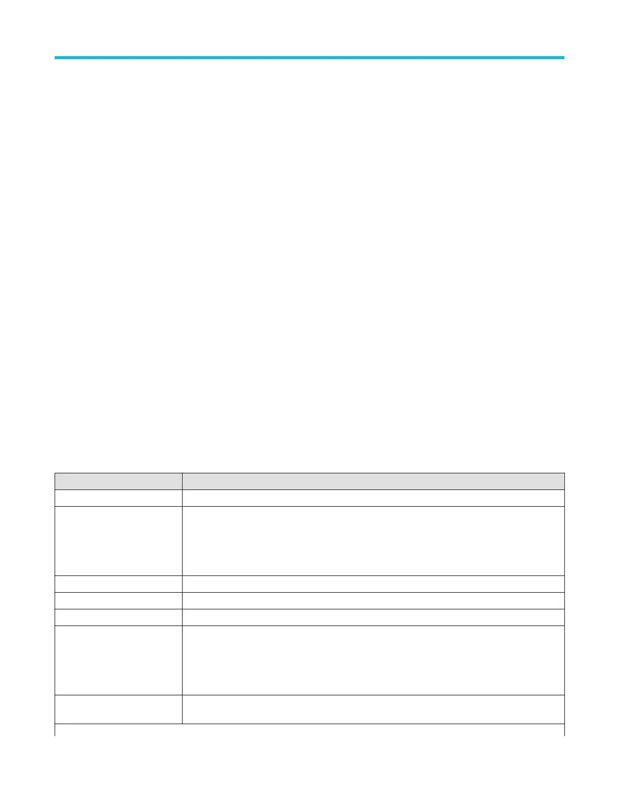
I2C serial bus menu fields and controls
Field or control Description
Display Turns on or off displaying the bus in the Waveform view.
Label Enter a label for the bus. The default label is the selected bus type.
T
o enter label text, double-tap the field and enter label using the virtual keyboard, or tap the field and
enter text from an attached keyboard.
Bus Type Set to I2C.
SCLK Input Sets the source and threshold level for the Serial Clock Line signal.
SDA Input Sets the source and threshold level for the Serial Data signal.
Include R/W bit in Address Select Yes to display 7-bit addresses as eight bits, where the eighth bit (LSB) is the R/W bit, or display
10-bit addresses as 11 bits, where the third bit is the R/W bit.
Select No to display 7-bit addresses as seven bits, and 10-bit addresses as ten bits.
Display Format Sets the waveform view to show just the decoded bus information, or the decoded bus and the logical
views of each constituent signal.
Table continued…
Menus and dialog boxes
3 Series Mixed Domain Oscilloscope Printable Help 123

 Loading...


